Sterling RT User Manual
Page 6
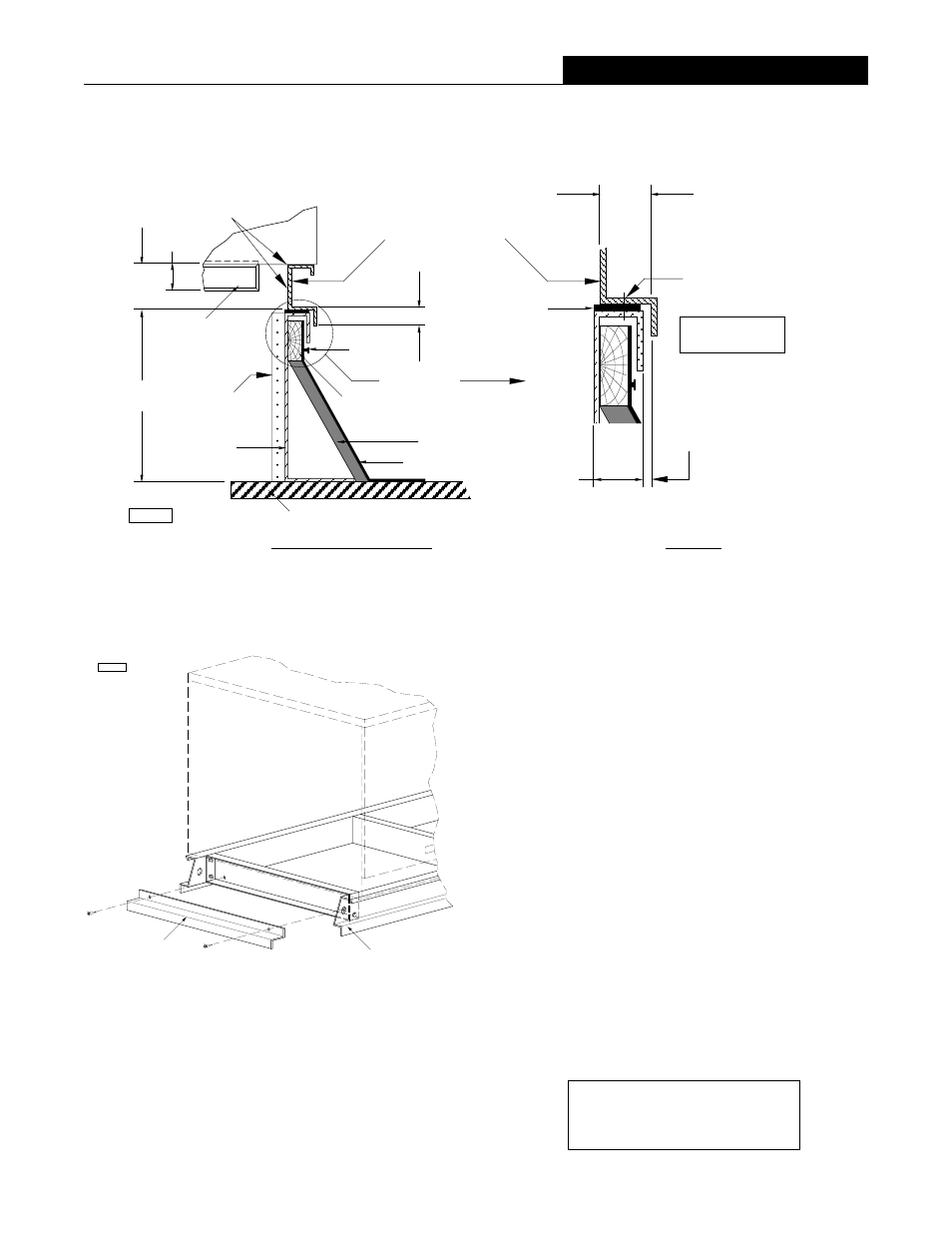
Figure 7 - Curb Specifications
Figure 8 - Unit/Curb Rail Assembly
2" (50)
3/8" (10) Clearance
Should Be Maintained
On Each Side To Insure
Proper Installation.
1-7/8" (22)
Anchor
Location
*
Field Supplied
By Others
D3809-2
4"
(102)
12"
(305)
Nailer
(Wood Strip)
Nail
*
Felt
*
Cant
*
1" (25)
Gasketing
Roof
Unit
Seal All Corners,
Seams & Gaps.
Unit Base
Side Rail Flange
With Curb Cap
Optional
Insulation
See Detail K
Detail K
Curb Rail
Ass'y.
Section Curb Side Rail
2-1/2"
(64)
Damper
D3809-3
Unit/Base Rail
Assembly
Curb Cap End Adaptor -
Supplied with the Unit
(one each end).
6
(U) RC001, (U)RC002, (U)RC003, (U)RC004, (U)RC006
For Field Installations: These Cross Brace/Curb
Adaptors (two adaptors ship with each rooftop unit) must
be repositioned when the unit is mounted on a curb or
platform (one for each end). Simply remove the screws,
turn the piece over (end for end) and secure in place
using the holes/hardware provided. All joints and
seams must be sealed completely to prevent leaks.
Replacement Hardware Kit:
Part No. RCHK-12346