Caution, Design considera, Opera – Sterling ERMS User Manual
Page 16: Opera operation tion tion tion tion
4
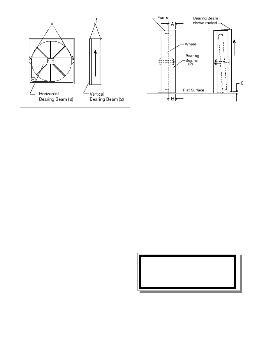
Figure 1 Lifting Hole Locations
Fig ure 2 Av oid Racking of Cassette Frame
CAUTION
Keep hands away from rotating wheel!!
Contact with rotating wheel can cause
physical injury.
DESIGN CONSIDERA
DESIGN CONSIDERA
DESIGN CONSIDERA
DESIGN CONSIDERA
DESIGN CONSIDERATIONS
TIONS
TIONS
TIONS
TIONS
Energy recovery cassettes can be incorporated within
the design of packaged rooftop units, packaged
airhandlers, energy recovery ventilators, or site built air
handling systems. In each case, it is recommended
that the following considerations be addressed
Accessibility
Accessibility
Accessibility
Accessibility
Accessibility
The cassette and all its operative parts; i.e.: motor,
belt, pulley, bearings, seals and energy transfer
segments must be accessible for service and
maintenance. The most practical design to allow
complete access is one in which the cassette can slide
at least half way out of the cabinet or ductwork for
service. This design requires that adequate clearance
be provided outside the enclosure.
Where cassettes are permanently installed in a
cabinet, access to both sides of the cassette must be
provided. Internal partitions that separate air streams
must allow access for bearing removal.
Orientation & Suppor
Orientation & Suppor
Orientation & Suppor
Orientation & Suppor
Orientation & Supporttttt
The Energy Recovery Cassette may be mounted in
any orientation. However, Care m
Care m
Care m
Care m
Care must be taken to
ust be taken to
ust be taken to
ust be taken to
ust be taken to
make cer
make cer
make cer
make cer
make certain that the cassette frame remains flat
tain that the cassette frame remains flat
tain that the cassette frame remains flat
tain that the cassette frame remains flat
tain that the cassette frame remains flat
and the bearing beams are not rac
and the bearing beams are not rac
and the bearing beams are not rac
and the bearing beams are not rac
and the bearing beams are not racked as sho
ked as sho
ked as sho
ked as sho
ked as shown in
wn in
wn in
wn in
wn in
Figure 2.
Figure 2.
Figure 2.
Figure 2.
Figure 2. To verify, make certain that the distance
between wheel rim and bearing beam is the same at
each end of the bearing beam, to within 1/4 of an inch
(dimension A & B, Fig. 2). This amount of racking can
be compensated for by adjusting the diameter seals
(see Fig. 3). If greater than 1/4 inc
If greater than 1/4 inc
If greater than 1/4 inc
If greater than 1/4 inc
If greater than 1/4 inch,
h,
h,
h,
h, rac
rac
rac
rac
racking m
king m
king m
king m
king must
ust
ust
ust
ust
be corrected to ensure that drive belt will not
be corrected to ensure that drive belt will not
be corrected to ensure that drive belt will not
be corrected to ensure that drive belt will not
be corrected to ensure that drive belt will not
disenga
disenga
disenga
disenga
disengag
g
g
g
ge fr
e fr
e fr
e fr
e from wheel.
om wheel.
om wheel.
om wheel.
om wheel.
Note: Bearing beam racking of as little as .040 inches
(Dim C, Fig. 2) will cause the wheel to tilt 3/16” at the
rim.
Diameter Seals
Diameter Seals
Diameter Seals
Diameter Seals
Diameter Seals
Diameter seals are adjusted at the factory when the
wheel is in the vertical position. Cassettes installed at
angles greater than 30 degrees from vertical will
require seal re-adjustment (see page 6, Figure 3).
Adjust diameter seals so as to avoid excessive wheel
drag. A final check of seal adjustment is
recommended for all designs.
Wheel Drive Motor
Wheel Drive Motor
Wheel Drive Motor
Wheel Drive Motor
Wheel Drive Motor
Cassette series 36 through 52 are provided with single
phase wheel drive motors (capacitor included). Single
phase motors may be pre-wired in the factory with
either a three pin Amp connector or three prong
NEMA plug. The motor is designed to rotate clockwise
when viewed from the shaft/pulley side.
Three phase wheel drive motors are provided with
optional 208/230V or 460/480V wiring. Motors may be
pre-wired in the factory upon request. Wiring
diagrams are provided with each motor. When wired
according to wiring diagram, motor rotates clockwise
when viewed from the shaft/pulley side.
OPERA
OPERA
OPERA
OPERA
OPERATION
TION
TION
TION
TION
Star
Star
Star
Star
Start Up Pr
t Up Pr
t Up Pr
t Up Pr
t Up Procedure
ocedure
ocedure
ocedure
ocedure
1.
By hand, turn wheel clockwise (as viewed from
the pulley side), to verify wheel turns freely
through 360º rotation.
2.
Before applying power to drive motor, confirm
wheel segments are fully engaged in wheel
Page 14 of 26
Page 16 of 28