Recommended oil supply systems, Booster pump, Figure 5 - loop system – Sterling QVOF User Manual
Page 5
5
RECOMMENDED
OIL SUPPLY SYSTEMS
BOOSTER PUMP
SETTING PRESSURE AND BLEEDING
FIGURES 4 AND 5
1. Stop all burner pumps.
2. Start boost pump manually
3. Set boost pump pressure so that gauge in first burner
manifold reads not more than 10 P.S.I.
4. Bleed air from first burner pump by loosening unused
inlet plug; bleed other units downstream the same
way.
5. Bleed manifold by loosening pipe cap (Figure 4).
6. For automatic operation, place switch on OFF.
Boost Pump Maximum Inlet Line (Ft.)
For Figures 4 & 5
Operation is extremely simple. Pressure developed by
oil burner fuel unit closes low-voltage switch connected
to it. This causes switch relay to energize boost pump
motor, which starts and stop automatically with burner.
For initial start-up, switch relay may be held “in”
manually. Or a manual ON/OFF switch can be
connected across low-voltage wires leading from switch
relay to pressure switch. With manual switch in “ON”
position, boost pump runs continuously.
NOTE: Check all burners for normal start and fuel
units for stable atomizing pressure. Then open boost
pump switch for automatic operation upon burner
demand.
Systems in Figures 4 and 5 will be in constant operation
when low-voltage switches are not used.
NOTE: Installations in figures 4 and 5 can be either
Intermittent or Constant operation.
CAUTION: When 2′ riser cannot be maintained, use
pressurized system in Figure 4.
Manifold and feeder lines must be run in a horizontal
plane and elevated above fuel unit intakes. At furnace
locations, extend feeder lines downward to fuel unit
intakes.
Install in accordance with National Board of Fire
Underwriters and local ordinances where applicable.
Figure 4 - Pressurized System
Boost
1/2″
1/2″
3/4″
Pump
Tube
Pipe
Pipe
30 GPH
300′
800′
2500′
50 GPH
175′
350′
1500′
Maximum Horizontal Line
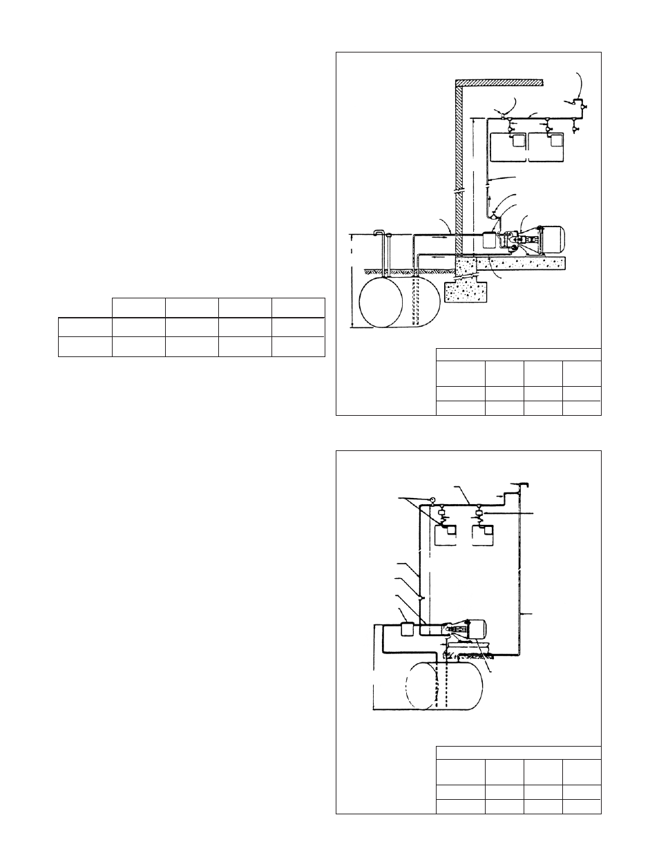
Figure 5 - Loop System
Boost
1/2″
1/2″
3/4″
Pump
Tube
Pipe
Pipe
30 GPH
300′
800′
2500′
50 GPH
175′
350′
1500′
Maximum Horizontal Line
Height
0-7′
10′
13′
15′
30 GPH
100′
80′
63′
52′
50 GPH
60′
53′
41′
34′
MANIFOLD AIR BLEED – HIGHEST POINT IN LINE
MAX INTAKE PRESSURE
AT BURNER 6 PSI
PIPE CAP
COMPOUND
GAUGE
MANIFOLD LINE
FEEDER
LINES
NO. 1
NO. 2
SUSPENDED FURNACES
FURNACE
NO. 3 ETC.
35 FT.
MAX
1/2" O.D. TUBING
1/2" O.D. TUBING
1/2" O.D. TUBING – INTAKE LINE
SHUT OFF VALVE
AUXILIARY FILTER
BOOST PUMP
AND MOTOR SET
TANK
"h"
15 FT.
MAX
MAX INTAKE GAUGE
PRESSURE AT FIRST
BURNER 6 PSI
MANIFOLD LINE
VENT
RISER
FEEDER
LINES
NO. 1
NO. 1
SUSPENDED FURNACES
OIL
SAFETY VALVES
35 FT.
MAX
1/2" O.D. TUBING
SHUTOFF VALVE
INLET
1/2" O.D. TUBING
AUXILIARY FILTER
1 1/4" PIPE
RETURN 1/2" O.D. TUBING
BOOST PUMP ASSEMBLY
TANK
15 FT.
MAX LIFT