Installation instructions – Sterling TD User Manual
Page 4
4
INSTALLATION INSTRUCTIONS
AIR INLET COLLAR
Remove screen and mounting plate from air inlet on top
panel of unit by removing 4 screws. Secure inlet collar
and gasket to inlet opening by reusing the 4 screws
removed in previous step.
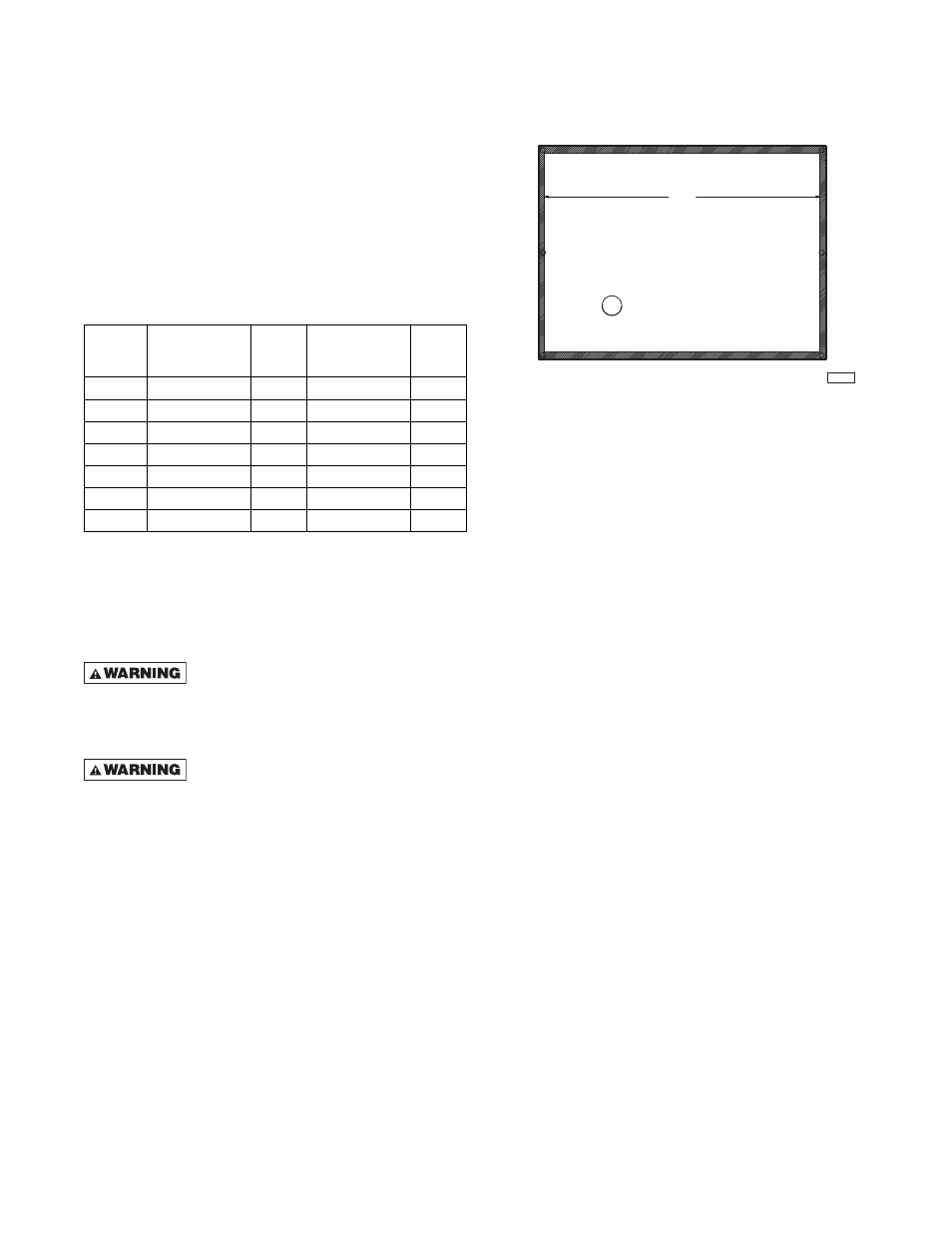
ACCESS PANEL SEAL
Cut gasket to lengths listed in Table 2. Remove paper
backing and adhere to access panel making certain
that the entire perimeter is covered (Figure 2).
Table 2 – Gasket Lengths
Figure 2 – Access Panel Seal
POWER SUPPLY INLET
After supply power line is run to main control board,
seal the gap between the cord and the hole in rear
panel with silicone sealant.
Unit
Size
Top/Bottom
Gasket Length
(In)
Qty
Right/Left
Gasket Length
(In)
Qty
100
8-3/4
2
28-1/8
2
150
12
2
28-1/8
2
200
15-1/4
2
28-1/8
2
250
18-1/2
2
28-1/8
2
300
21-3/4
2
28-1/8
2
350
25
2
28-1/8
2
400
28-1/4
2
28-1/8
2
28.125
D9451
TOP
BOTTOM
SIDE
SIDE
VENTING FOR SEPARATED COMBUSTION DUCT FURNACES
(CATEGORY III)
COMBUSTION AIR
Never operate separated combustion
duct furnaces without combustion air and fl ue gas
piping in place or severe personal injury or death
may occur!
CARBON MONOXIDE!
Your venting system must not be blocked by any
snow, snow drifts, or any foreign matter. Inspect
your venting system to ensure adequate ventilation
exists at all times! Failure to heed these warnings
could result in Carbon Monoxide Poisoning (symp-
toms include grogginess, lethargy, inappropriate
tiredness, or fl u-like symptoms).
1. In the United States, the combustion air system
installation must be in accordance with the latest
edition of ANSI Z223.1 (NFPA 54) National Fuel
Gas Code. In Canada, installation must be in
accordance with CSA-B149.1 “Installation Code for
Natural Gas Burning Appliances and Equipment”
and CSA-B149.2 “Installation Code for Propane
Burning Appliances and Equipment.”
2. A Breidert Type L or Fields Starkap, furnished by
the customer, must be installed at the termination
point of the combustion air system. See Figures
3a and 3b.
3. Each duct furnace MUST have its own combustion
air system. It MUST NOT be connected to other air
intake systems.
4. Combustion air intake duct may be PVC, CPVC,
Type B vent, single wall, double wall or other
material approved by local code authority.
Never use duct size other than the diameter
stated in these instructions.
5. Long runs of single wall combustion air piping
passing through an unheated space may require
insulating if condensation becomes noticeable.
6. The combustion air system must be installed to
prevent collection of condensate. Pitch horizontal
pipes downward 1/4" per foot (21mm/m) toward the
inlet cap to facilitate drainage. Vertical combustion
air pipes should be piped as depicted in Figure 3a.
7. The equivalent length of the combustion air system
must not be less than 5 feet (1.5m) and must not
exceed 50 feet (15.2m). Equivalent length equals
the total length of straight pipe, plus 10 feet (3.05m)
for each 90° elbow and 4 feet (1.22m) for each
45° elbow.
NOTICE: For optimum performance keep the com-
bustion air system as straight as possible.