Maintenance, calibration apparatus, 2 calibration procedure – Yokogawa JUXTA FS1V Potentiometer Converter User Manual
Page 4
4
IM 77J08S01-01E 1st Edition
2008.01.15-00
6. MAINTENANCE
The product starts running immediately when the power is turned
on; however, it needs 10 to 15 minutes of warm-up before it
meets the specified performance.
6. Calibration Apparatus
6-dial decade resistance boxes x 2 units
(Yokogawa Meters & Instruments 279301 or equivalent)
A digital multimeter, DMM (Yokogawa 7561 or equivalent)
A precision resistor of 250 Ω ±0.01%, 1W
A setting tool for adjustment (Refer to "4. Setting Parameters"
in this manual)
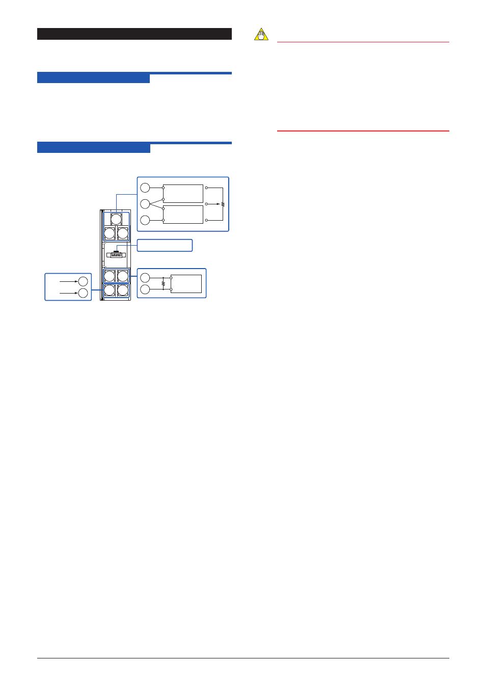
6.2 Calibration Procedure
1. Connect the instruments as shown below.
1
2
3
4
5
6
7
6
7
4
5
Setting tool
Output
24V DC
Power supply
Ro
Ro: a precision resistor 250 Ω
(in case of current output)
DMM
1
R1
R1
100%
0%
R2
R2
2
3
6-dial decade
resistance box
Input
6-dial decade
resistance box
2 Keeping total resistance constant, change each value of R1
and R2 to apply the resistance equivalent to 0, 25, 50, 75, and
100% of the input range to the converter.
3. Verify that the corresponding output voltages are 0, 25, 50, 75,
and 100% respectively and within the specified accuracy rating.
(Ro is used for current output.)
Use the setting tool (VJ77 Parameter Setting Tool or JHT200
Handy Terminal) to adjust the input/output signals.
Input Adjustment Procedure
(1)
Set the total resistance of the potentiometer being
combined, to the parameter
[B08: RESIST].
(2)
From the potentiometer, input the value equivalent to 0%
value of the input range to the converter.
(3)
Read the parameter [C06: ZERO ADJ] and check the
input value.
(4)
Fix the value, where
[C06: ZERO ADJ] is displayed.
a. When adjusting by the JHT200, press
twice.
b. When adjusting by the VJ77, click the
[WRITE]
button.
(5)
Input the value equivalent to 100% value of the input
range to the converter from the potentiometer on site.
(6)
Read the parameter
[C07: SPAN ADJ] and check the
input value.
(7)
Fix the value, where
[C07: SPAN ADJ] is displayed.
a. When adjusting by the JHT200, press
twice.
b. When adjusting by the VJ77, click the
[WRITE]
button.
NOTE
● The set value of the input range is automatically
updated after the input adjustment.
The adjustment value of [C06: ZERO ADJ] is
overwritten in [B10: ZERO], and that of [C07: SPAN
ADJ] is overwritten in [B11: SPAN], respectively.
● For the input adjustment, do not use the calibration
apparatus but the potentiometer actually connected
to this converter. The adjustment using the
calibration apparatus causes the measurement error.
Output Adjustment Procedure
When adjusting 0% value of output:
(1) Set the adjustment value 0% in the parameter
[C0:
OUT 0%].
•The value equivalent to 0% of the output range will be
output, irrespective of the input.
(2) Check the output value via digital multimeter, and adjust
it in the parameter
[C0: OUT 0%].
•If the indicating value of DMM deviates to the (+) side,
set (−) value equivalent to the deviation; if it deviates to
the (−) side, set (+) value equivalent to the deviation for
adjusting the output value to 0%.
*: The 100% value of output can be adjusted by the same
operation as the above in
[C02: OUT00%]
For adjustment using a setting tool, refer to the User’s Manual for
each setting tool and “5. List of Parameters” in this manual.
Use the VJ77 of version R1.05 or later.
User’s Manual for the VJ77 [Document No.: IM 77J01J77-01E]
User’s Manual for the JHT200 [Document No.: IM JF81-02E]