External wiring, Maintenance, Warning – Yokogawa JUXTA FA4V Distributor (Non-isolated) User Manual
Page 3: 1 calibration apparatus, 2 calibration procedure
3
IM 77J08A04-01E 1st Edition
Nov, 18. 2011-00
3. EXTERNAL WIRING
WARNING
Be sure to turn OFF the power supply before wiring to
avoid the risk of electric shock. Use a tester or similar
device to ensure that no power is being supplied to a
cable to be connected.
M4 screw terminals are provided for the connection of external
signals. Attach a crimp-on lug to each wire for connection to the
terminals.
• Recommended cables: A nominal cross-sectional area of
0.5 mm
2
or thicker for signal cables, and that of 1.25 mm
2
or
thicker for power cables.
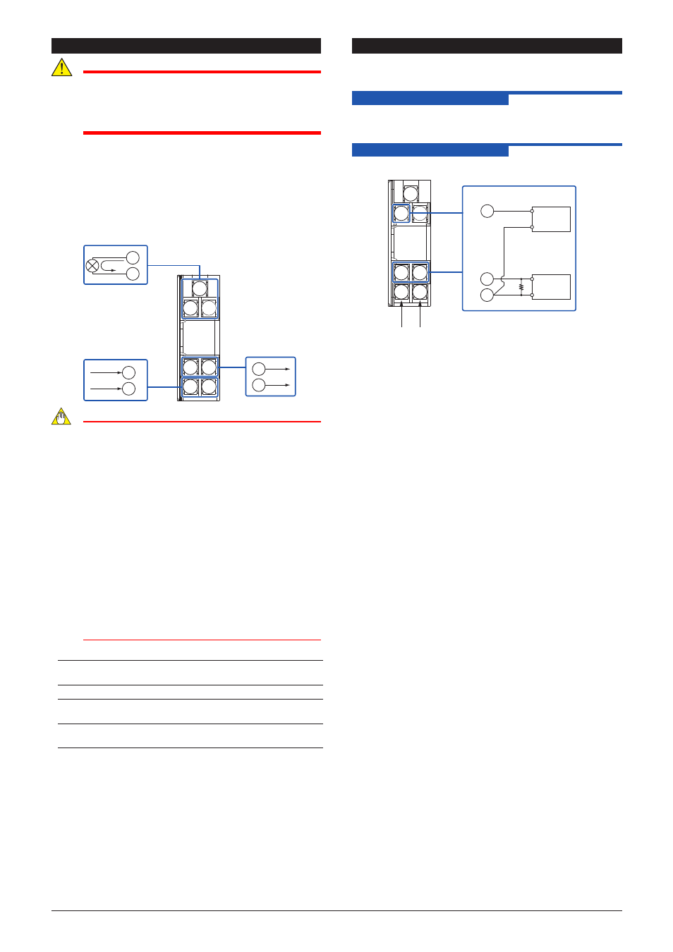
Wiring Diagram
1
2
4
5
6
7
6
7
4
5
+
−
Output
Input
Power Supply
+
–−
1
2
PS+
−
+
−
NOTE
●
Do not connect anything to the terminals that are
not used in the wiring diagram. Otherwise it may
cause the malfunction or damage.
●
The power line and input/output signal lines should
be installed away from noise-generating sources.
Otherwise accuracy cannot be guaranteed.
●
Adhere strictly to the specifications to avoid
overheating or damage. Before turning on the
power, ensure the following:
•
•
Power supply voltage and input signal value
applied to the product should meet the required
specifications.
•
•
The external wiring to the terminals and wiring to
ground are as specifications.
●
Do not operate the product in the presence of
flammable or explosive gases or vapors.
●
This product is sensitive to static electricity;
exercise care in handling. Before you operate the
product, touch a nearby metal part to discharge
static electricity.
Power Supply and Isolation
Power supply voltage: 24 V DC±10% (percentage ripple: less
than 5% p-p)
Current consumption : 65 mA
Insulation resistance: 100 MΩ at 500 V DC between (input and
output) and power supply.
Withstand voltage:
500 V AC/min. between (input and output)
and power supply
4. MAINTENANCE
The product starts running immediately when the power is turned
on; however, it needs 10 to 15 minutes of warm-up before it
meets the specified performance.
4.1 Calibration Apparatus
• A voltage current source (Yokogawa GS200 or equivalent)
• A digital multimeter, DMM (Yokogawa 7561 or equivalent)
• A precision resistor of 250 Ω±0.01%, 1W
4.2 Calibration Procedure
1. Connect the instruments as shown below.
1
2
4
5
6
7
2
4
5
+
–
+
–
Ro
DMM
L+ N–
Power
supply
24V DC
Voltage
current
source
Ro: a precision resistor 250Ω
Input
Output
Ro is used for current output (FA4A).
2. Use the voltage current source and apply the electromotive
force equivalent to 0, 25, 50, 75, and 100% of the measuring
range to the distributor.
3. Verify that the corresponding output voltages are 0, 25, 50,
75, and 100% respectively and within the specified accuracy
rating.