Part names of front panel, Example of usage, Explanation of operation – Yokogawa JUXTA ML2 User Manual
Page 3
3
IM 77J04L02-01E
1st Edition Sep.10, 2004-00
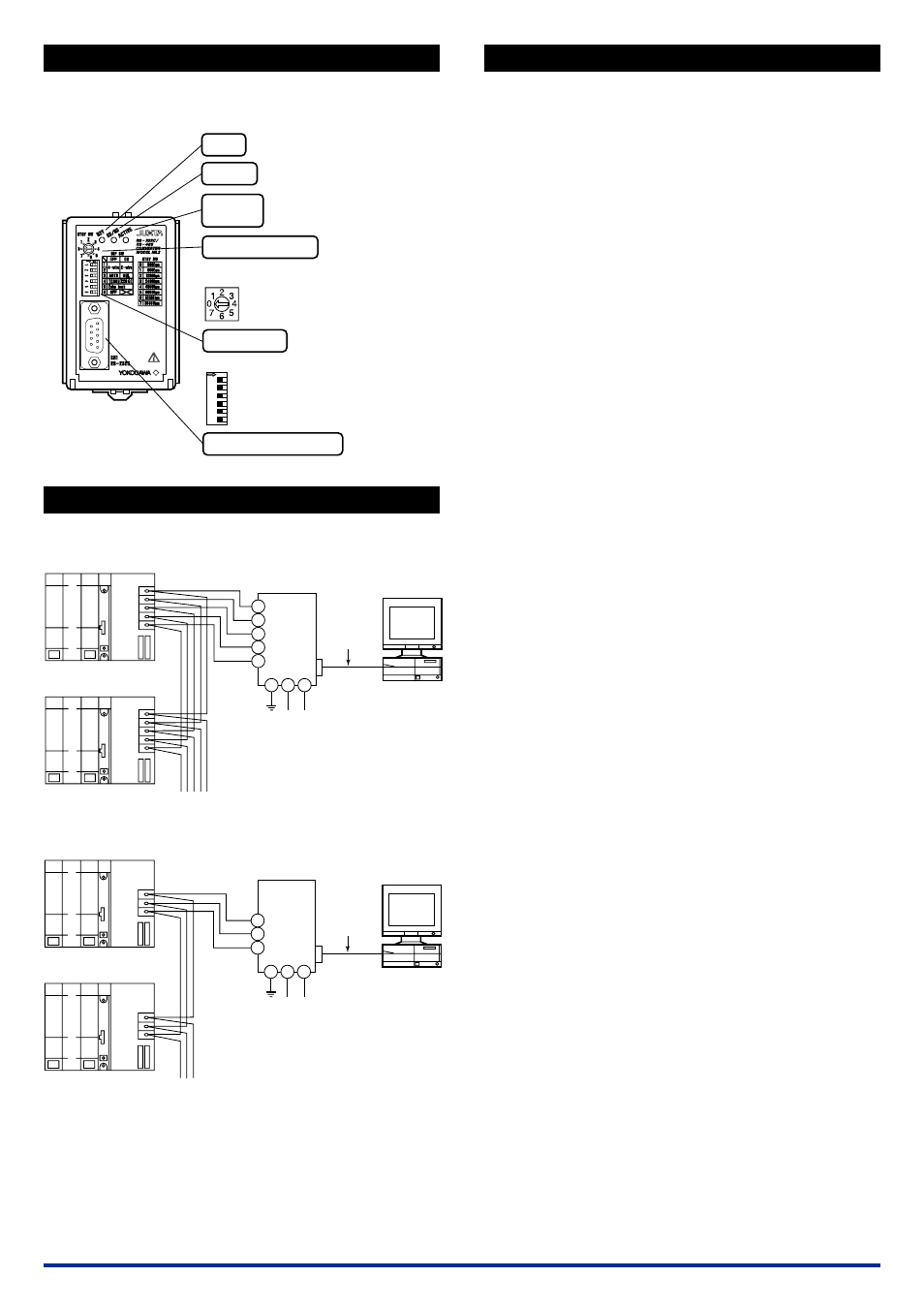
7. PART NAMES OF FRONT PANEL
The product starts running immediately when the power is turned on;
however, it needs 10 to 15 minutes of warm-up before it meets the
specified performance.
Lit in green while the power is turned on
DIP SWITCH
RDY
Lit in green when data is received in
RXD of RS-232C side
Lit in green while the driver is
active
SD/RD
D-sub 9-pin connector (male)
Set the switch in accordance with each setting.
Left: OFF
Right: ON
Set the switch in accordance with communication
speed.
RS-232C CONNECTOR
DRIVER
ACTIVE
ROTARY SWITCH
ON
12
34
5
6
8. EXAMPLE OF USAGE
●
4-wire
1
RDA(-)
RDB(+)
SDA(-)
SDB(+)
SG
RDA(-)
RDB(+)
SDA(-)
SDB(+)
SG
To other RS-485 instrument
2
3
SDA (-)
SDB (+)
RDA (-)
4
5
RDB (+)
SG
6 8
Power Supply
Upper Computer
ML2
RS-232C
(Straight
Cable)
RS-485
7
●
2-wire
A(-)
B(+)
SG
A(-)
B(+)
SG
3
A (-)
4
5
B (+)
SG
6 8
ML2
RS-485
7
Power Supply
Upper Computer
RS-232C
(Straight
Cable)
To other RS-485 instrument
9. EXPLANATION OF OPERATION
9.1
Signal Transmit Mode (Start bit detection timer
mode)
(a) RS-232C
→
RS-485
●
When RS-485 Driver Active is in Auto
When start bit is detected on RS-232C side (Send Data becomes
logic 0), the converter makes RS-485 driver active, and transmits
data of RS-232C side to RS-485 side.
When Send Data of RS-232C becomes no data (logic 1), the con-
verter starts timer of 10 bits*
1
and maintains RS-485 driver active
until time-up. After time-up, the converter returns RS-485 driver
to passive to stop transmission.
●
When RS-485 Driver Active is in Manual
When RS (Request to Send) of RS-232C side is turned on (logic
0), the converter makes RS-485 driver active and transmits data
of RS-232C side to RS-485 side. It maintains RS-485 driver ac-
tive while RS (Request to Send) is turned on.
When RS (Request to Send) is turned off, the converter returns
RS-485 driver to passive to stop transmission.
(b) RS-485
→
RS-232C
●
When start bit (logic 0) is detected on RS-485 side, the converter
turns off CS (Clear to Send) of RS-232C side and transmits data
of RS-485 side to RD (Receive Data) of RS-232C side.
When data of RS-485 side becomes logic 1, the converter starts
timer of 10 bits*
1
and maintains CS (Clear to Send) of RS-232C
side off until time-up. After time-up, the converter turns on CS
(Clear to Send) to stop transmission.
*1: Equivalent to 10 bits of communication speed set to the
converter.
9.2
Counterplan for Connections to RS-485 Instru-
ments Having Quick Response
When starting up system or when newly adding connection of instru-
ments, if RS-485 response is quick, communication may sometimes
not be carried out smoothly.
RS-232C
→
RS-485
When active control of RS-485 driver is set to Auto, RS-485 driver
is in active state for elapsed time of 10 bits after RS-232C data
becomes none. During this interim, even if RS-485 having quick
response generates signal, RS232C/RS485 converter cannot en-
sure transmit signal. Example of counterplan against this state is
as mentioned below:
Example 1
Set the active control of RS-485 driver to Manual. At upper com-
puter side connected with RS-232C, make synchronization of
data transmit and RS (Request to Send). When data transmit
completes, make RS-485 driver passive immediately.
Example 2
Set the communication setting time of RS232C/RS485 converter
shorter (faster) than data transmit speed.
However, in this case, fail safe circuit should be included in every
function of RS-485 connected with this converter. (In order to
make the fail safe circuit of communication opponent recognize
the disabled state after timer cut off.)
When data from RS-485 instrument is transmitted to RS-232C,
because CS (Clear to Send) turns on during data transmission,
upper computer connected with RS-232C should incorporate
communication sequence so as to enter transmit state after re-
ceiving data up to the end.