Maintenance, 1 calibration apparatus, 2 calibration procedure – Yokogawa JUXTA MA5D User Manual
Page 5
5
IM 77J04A05-02E
1st Edition
Jul 29, 2005-00
7. MAINTENANCE
The product starts running immediately when the power is turned on;
however, it needs 10 to 15 minutes of warm-up before it meets the
specified performance.
7.1
Calibration Apparatus
●
A DC voltage/current standard (Yokogawa 7651 or the equivalent)
●
A digital mutimeter (Yokogawa 7561 or the equivalent)
●
A precision resistor of 250
Ω
±
0.01%, 1 W
●
A setting tool for adjustment
(Refer to “ 4.2 Connector for Communication” in this manual.)
7.2
Calibration Procedure
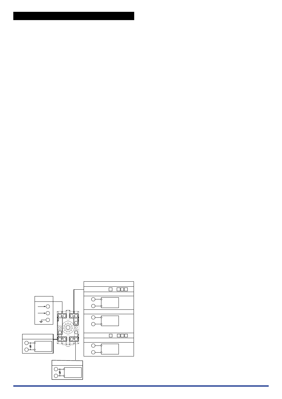
(1) Connect the instruments as shown below. First adjust the output-1
signal and then the output-2 signal.
(2) Use the DC voltage/current standard and apply input signals
equivalent to 0, 25, 50, 75, and 100% of input span to the distribu-
tor. When “with square root extractor” is selected, apply input sig-
nals equivalent to 0, 6.25, 25, 56.25, and 100% of input span to
the distributor.
(3) Check to see the corresponding output voltages are 0, 25, 50, 75,
and 100% respectively and within the specified accuracy rating.
“R” is used for current output.
●
Use the setting tool (VJ77 Parameter Setting Tool or JHT200
Handy Terminal) or the switches on the front panel (selection
switch and adjustment switch) to adjust the input/output signals.
Input Adjustment Procedure
(1) Input the value equivalent to 0% value of input range.
(2) Call the display item (A: DISPLAY1) to check the input value in
A01: INPUT1.
(3) If the adjustment is necessary, call the adjustment item (P: AD-
JUST).
(4) Select P08: IN1 ZERO ADJ to enter the adjustment mode. Select
EXECUTE (adjustment) for adjustment. (If RESET is selected,
the adjusted value is reset to the factory-set default.)
(5) Input the value equivalent to 100% value of input range.
(6) Call the display item (A: DISPLAY1) to check the input value in
A01: INPUT1.
(7) If the adjustment is necessary, call the adjustment item (P: AD-
JUST).
(8) Select P09: IN1 SPAN ADJ to enter the adjustment mode. Select
EXECUTE (adjustment) for adjustment. (If RESET is selected,
the adjusted value is reset to the factory-set default.)
Output Adjustment Procedure
(1) When adjusting 0% value of output-1, call the adjustment item (P:
ADJUST) to select P26: OUT1ZERO ADJ.
(2) If it slips out to (
+
) side, set (
−
) value equivalent to slipout; if slips
out to (
−
) side, set (
+
) value equivalent to slipout.
*:
The 100% value of output-1 and the 0% value and 100% value of
output-2 can be adjusted by the same operation as the above.
For adjustment using a setting tool, refer to the User’s Manual for
each setting tool and “6. List of Parameters” in this manual.
For adjustment using the switches on the front panel, refer to “4.3
Selection Switch and Adjustment Switch.”
User’s Manual for VJ77 [Document No.: IM 77J01J77-01E]; how-
ever, use the VJ77 of version R1.04 or later.
User’s Manual for JHT200 [Document No.: IM JF81-02E]
10 11
1
2
3
9
8
7
6
5
4
DC voltge/
current
standard
L
+
N
−
GND
9
7
8
1
2
R
R
4
5
−
+
DC voltge/
current
standard
6
5
−
+
DC voltge/
current
standard
−
+
−
+
−
+
5
6
R: 250
Ω
precision resistor
for current output
R: 250
Ω
precision resistor
for current output
Power supply
Output-2
Input
With SINK current
With SINK current
Without SINK current
Output-1
Digital
multimeter
Digital
multimeter
MA5D - 02 -A
MA5D - 12 -A
10
11