Setting parameters, List of parameters, 1 setting square root extractor – Yokogawa JUXTA MA5 User Manual
Page 4: 2 setting lowcut point, 3 setting breakpoint linearization, 4 setting output range
4
IM 77J04A05-01E
1st Edition
Jul 29, 2005-00
5. SETTING PARAMETERS
Set the parameters using a PC (VJ77 Parameter Setting Tool) or the
Handy Terminal. Refer to “6. List of Parameters” in this manual and the
User’s Manual for VJ77 PC-based Parameters Setting Tool (IM
77J01J77-01E) or the User’s Manual for JHT200 Handy Terminal (IM
JF81-02E). Parameters are indicated inside the [ ].
5.1
Setting Square Root Extractor
Set "with square root extractor" or "without square root extractor" in
[D14: LINEARIZE]. "SQR" for "with square root extractor" and "OFF"
for "without square root extractor"
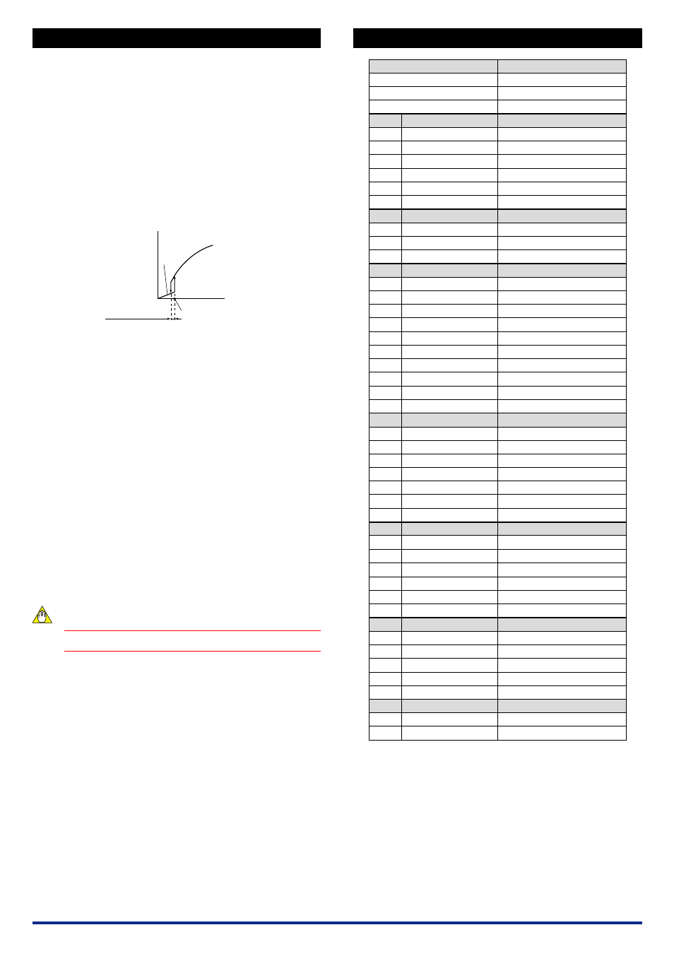
5.2
Setting Lowcut Point
Set a numeric value in [D15:LOW CUT] when “with square root extrac-
tor” is selected.
●
Setting range: 0.3 to 100% of the input range (setting resolution:
0.1%)
Input signal (X)
Output signal
(Y)
0
Lowcut point
Hysteresis
(approx. 0.2% fixed)
Y=X
5.3
Setting Breakpoint Linearization
(1) Set the breakpoint linearization in [D14: LINEARIZE].
Select “ON” to use the breakpoint linearization.
Select “OFF” not to use the breakpoint linearization.
(2) Set the breakpoints data.
Set the input breakpoints data in [M01: X TABLE] to [M32: X
TABLE].
Set the number of breakpoints data in [M33: MAX POINT].
Set the output breakpoints data in [N01: Y TABLE] to [N32: Y
TABLE].
●
Setting condition of breakpoints data
Maximum number of breakpoints: 32
Setting range:
−
6 to 106% (both input and output)
• Set a relationship between the input and outpout at % value to
the span.
• With 4 significant digits; can be set to the second place of a
decimal point.
• For input:
−
6.00
Ϲ
X
0
Ͻ
X
1
Ͻ
X
2
…X
n-1
Ͻ
X
n
Ϲ
106.0%
• For output:
−
6.00
Ϲ
Y
0
to Y
n
Ͻ
106.0%
5.4
Setting Output Range
Set the 0% value of output range in [D38: OUT1 L_RNG] and the
100% value of output range in [D39: OUT1 H_RNG].
NOTE
Changing the output range resets the adjusted value.
6.
LIST OF PARAMETERS
A
A01
A07
A54
A56
A58
A60
B
B01
B07
B60
D
D01
D02
D03
D04
D14
D15
D38
D39
D49
D60
M
M01
M02
:
M31
M32
M33
M60
N
N01
N02
:
N31
N32
N60
P
P08
P09
P26
P27
P60
Q
Q03
Q60
MODEL
TAG NO
SELF CHK
DISPLAY1
INPUT1
OUTPUT1
STATUS
REV NO
MENU REV
SELF CHK
DISPLAY2
INPUT1
OUTPUT1
SELF CHK
SET (I/O)
TAG NO.1
TAG NO.2
COMMENT1
COMMENT2
LINEARIZE
LOW CUT
OUT1 L_RNG
OUT1 H_RNG
OUT1 DR
SELF CHK
X TABLE
X TABLE
X TABLE
:
X TABLE
X TABLE
MAX POINT
SELF CHK
Y TABLE
Y TABLE
Y TABLE
:
Y TABLE
Y TABLE
SELF CHK
ADJUST
IN1 ZERO ADJ
IN1 SPAN ADJ
OUT1ZERO ADJ
OUT1SPAN ADJ
SELF CHK
TEST
OUT1 TEST
SELF CHK
Model
Tag number
Self-check result
Display1
Input-1
Output-1
Status
*1
REV No.
MENU REV
Self-check result
Display2
Input-1
Output-1
Self-check result
Setting (I/O)
Tag number-1
Tag number-2
Comment-1
Comment-2
Linearization
Lowcut point
*2
Output-1 low range
Output-1 high range
Direction of output-1 action
Self-check result
Input breakpoint table
Input breakpoints data
Input breakpoints data
:
Input breakpoints data
Input breakpoints data
Number of breakpoints
Self-check result
Output breakpoint table
Output breakpoints data
Output breakpoints data
:
Output breakpoints data
Output breakpoints data
Self-check result
Adjustment
Input-1 zero adjustment
Input-1 span adjustment
Output-1 zero adjustment
Output-1 span adjustment
Self-check result
Test
Forced output-1
Self-check result
Parameter Display
Item
*1 The displayed status is to let the service staff know the past records of the
product.
*2 The parameter becomes effective when "SQR" is selected in [D14:LINEARIZE].