Setting parameters, List of parameters, 1 setting square root extractor – Yokogawa JUXTA MH5D User Manual
Page 4: 2 setting lowcut point, 3 setting breakpoint linearization, 4 setting input range, 5 setting output-1 range
4
IM 77J04H05-02E
1st Edition
Jul 29, 2005-00
5. SETTING PARAMETERS
Set the parameters using a PC (VJ77 Parameter Setting Tool) or the
Handy Terminal. Refer to “6. List of Parameters” in this manual and the
User’s Manual for VJ77 PC-based Parameters Setting Tool (IM
77J01J77-01E) or the User’s Manual for JHT200 Handy Terminal (IM
JF81-02E). Parameters are indicated inside the [ ].
5.1
Setting Square Root Extractor
Set “with square root extractor” or “without square root extractor” in
[D14: LINEARIZE]. “SQR” for “with square root extractor” and “OFF”
for “without square root extractor.”
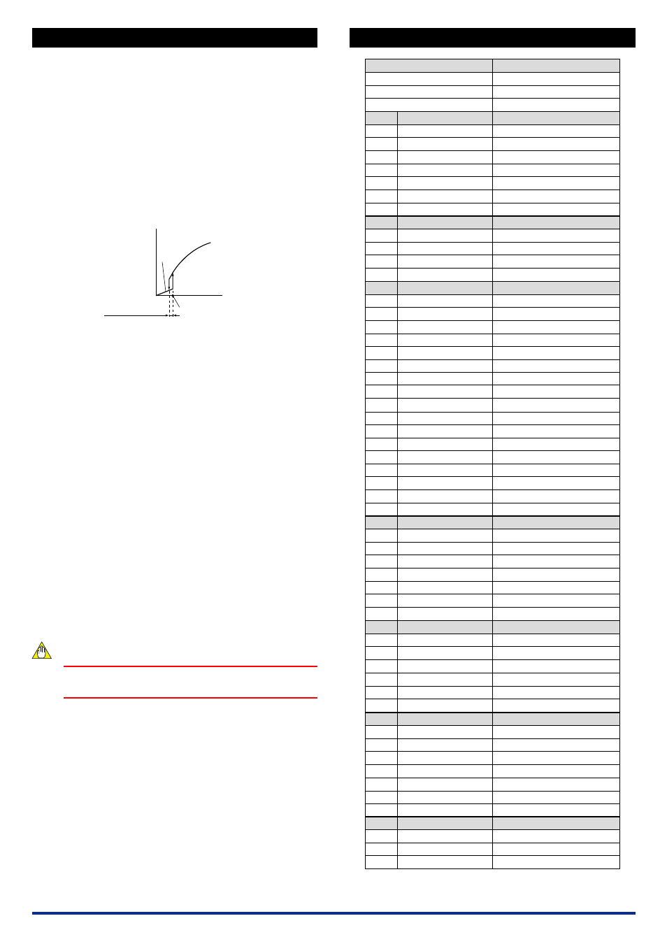
5.2
Setting Lowcut Point
Set a numeric value in [D15:LOW CUT] when “with square root extrac-
tor” is selected.
●
Setting range: 0.3 to 100% of the input range (setting resolution:
0.1%)
Input signal (X)
Output signal
(Y)
0
Lowcut point
Hysteresis
(approx. 0.2% fixed)
Y=X
5.3
Setting Breakpoint Linearization
(1) Set the breakpoint linearization in [D14: LINEARIZE].
Select “ON” to use the breakpoint linearization.
Select “OFF” not to use the breakpoint linearization.
(2) Set the breakpoints data.
Set the input breakpoints data in [M01: X TABLE] to [M32: X
TABLE].
Set the number of breakpoints data in [M33: MAX POINT].
Set the output breakpoints data in [N01: Y TABLE] to [N32: Y
TABLE].
●
Setting condition of breakpoints data
Maximum number of breakpoints: 32
Setting range:
−
6 to 106% (both input and output)
• Set a relationship between the input and outpout at % value to
the span.
• With 4 significant digits; can be set to the second place of a
decimal point.
• For input:
−
6.00
Ϲ
X
0
Ͻ
X
1
Ͻ
X
2
…X
n-1
Ͻ
X
n
Ϲ
106.0%
• For output:
−
6.00
Ϲ
Y
0
Ͻ
Y
1
to Y
n
Ͻ
106.0%
5.4
Setting Input Range
Set the input range 0% in [D27:INPUT1 L_RNG], and the input range
100% in [D28:INPUT1 H_RNG].
5.5
Setting Output-1 Range
Set the output-1 range 0% in [D38:OUT1 L_RNG], and the output-1
range 100% in [D39:OUT1 H_RNG].
NOTE
Changing the input range or output-1 range resets the
adjusted value.
6.
LIST OF PARAMETERS
A
A01
A07
A08
A54
A56
A58
A60
B
B01
B07
B08
B60
D
D01
D02
D03
D04
D14
D15
D20
D22
D27
D28
D38
D39
D40
D41
D49
D50
D60
M
M01
M02
:
M31
M32
M33
M60
N
N01
N02
:
N31
N32
N60
P
P08
P09
P26
P27
P28
P29
P60
Q
Q03
Q04
Q60
MODEL
TAG NO
SELF CHK
DISPLAY1
INPUT1
OUTPUT1
OUTPUT2
STATUS
REV NO
MENU REV
SELF CHK
DISPLAY2
INPUT1
OUTPUT1
OUTPUT2
SELF CHK
SET (I/O)
TAG NO.1
TAG NO.2
COMMENT1
COMMENT2
LINEARIZE
LOW CUT
INP TYPE
IN RESIST
INPUT1 L_RNG
INPUT1 H_RNG
OUT1 L_RNG
OUT1 H_RNG
OUT2 L_RNG
OUT2 H_RNG
OUT1 DR
OUT2 DR
SELF CHK
X TABLE
X TABLE
X TABLE
:
X TABLE
X TABLE
MAX POINT
SELF CHK
Y TABLE
Y TABLE
Y TABLE
:
Y TABLE
Y TABLE
SELF CHK
ADJUST
IN1 ZERO ADJ
IN1 SPAN ADJ
OUT1ZERO ADJ
OUT1SPAN ADJ
OUT2ZERO ADJ
OUT2SPAN ADJ
SELF CHK
TEST
OUT1 TEST
OUT2 TEST
SELF CHK
Model
Tag number
Self-check result
Display1
Input-1
Output-1
Output-2
Status
*1
REV No.
MENU REV
Self-check result
Display2
Input-1
Output-1
Output-2
Self-check result
Setting (I/O)
Tag number-1
Tag number-2
Comment-1
Comment-2
Linearization
Lowcut point
*2
Input type
*3
Input resistance
*3
Input-1 low range
Input-1 high range
Output-1 low range
Output-1 high range
Output-2 low range
*3
Output-2 high range
*3
Direction of output-1 action
Direction of output-2 action
Self-check result
Input breakpoints table
Input breakpoints data
Input breakpoints data
:
Input breakpoints data
Input breakpoints data
Number of breakpoints
Self-check result
Output breakpoints table
Output breakpoints data
Output breakpoints data
:
Output breakpoints data
Output breakpoints data
Self-check result
Adjustment
Input-1 zero adjustment
Input-1 span adjustment
Output-1 zero adjustment
Output-1 span adjustment
Output-2 zero adjustment
Output-2 span adjustment
Self-check result
Test
Forced output-1
Forced output-2
Self-check result
Parameter Display
Item
*1 The displayed status is to let the service staff know the past records of the
product.
*2 The parameter becomes effective when "SQR" is selected in [D14:LINEARIZE].
*3 The parameters are the items to be set at the factory.