Yokogawa JUXTA MH5 User Manual
User’s manual, Checking product specifications and packaged items, General
User’s
Manual
Network Solutions Business Division
2-9-32, Naka-cho Musashino-shi, Tokyo 180-8750 Japan
Phone: +81-422-52-7179
Facsimile: +81-422-52-6793
1
Please read through this User’s Manual before use for correct handling.
Please keep this User’s Manual for future reference.
Model MH5
Isolator
(Free Range Type)
CAUTIONARY NOTES FOR SAFE USE OF THE PRODUCT
This User’s Manual should be carefully read before installing and oper-
ating the product. The following symbol is used on the product and in
this manual to ensure safe use.
This symbol is displayed on the product when it is
necessary to refer to the User’s Manual for information on
personnel and instrument safety. This symbol is displayed
in the User’s Manual to indicate precautions for avoiding
danger to the operator, such as an electric shock.
The following symbols are used only in this manual.
IMPORTANT
Indicates that operating the hardware or software in a
particular manner may cause damage or result in a system
failure.
NOTE
Draws attention to essential information for understanding
the operations and/or functions of the product.
CHECKING PRODUCT SPECIFICATIONS AND PACKAGED ITEMS
(1) Checking the Model and Product Specifications
Check that the model and specifications indicated on the nameplate
attached to the main unit are as ordered.
(2) Packaged Items
Check that the package contains the following items:
●
MH5: 1
●
Receiving resistor (for currrent input): 1
●
Spacer (for DIN rail mounting): 1
●
Range label: 1
●
User’s Manual (this manual: IM 77J04H05-01E): 1
✻
The 250
Ω
receiving resistor is attached for the optional specifica-
tion “/R250”; the 100
Ω
receiving resistor is attached for the op-
tional specification “/R100.”
GENERAL
The MH5 is a plug-in type isolator that converts DC current or DC volt-
age signals into isolated DC current or DC voltage signals.
IM 77J04H05-01E
1st Edition Jul. 2005 (YK)
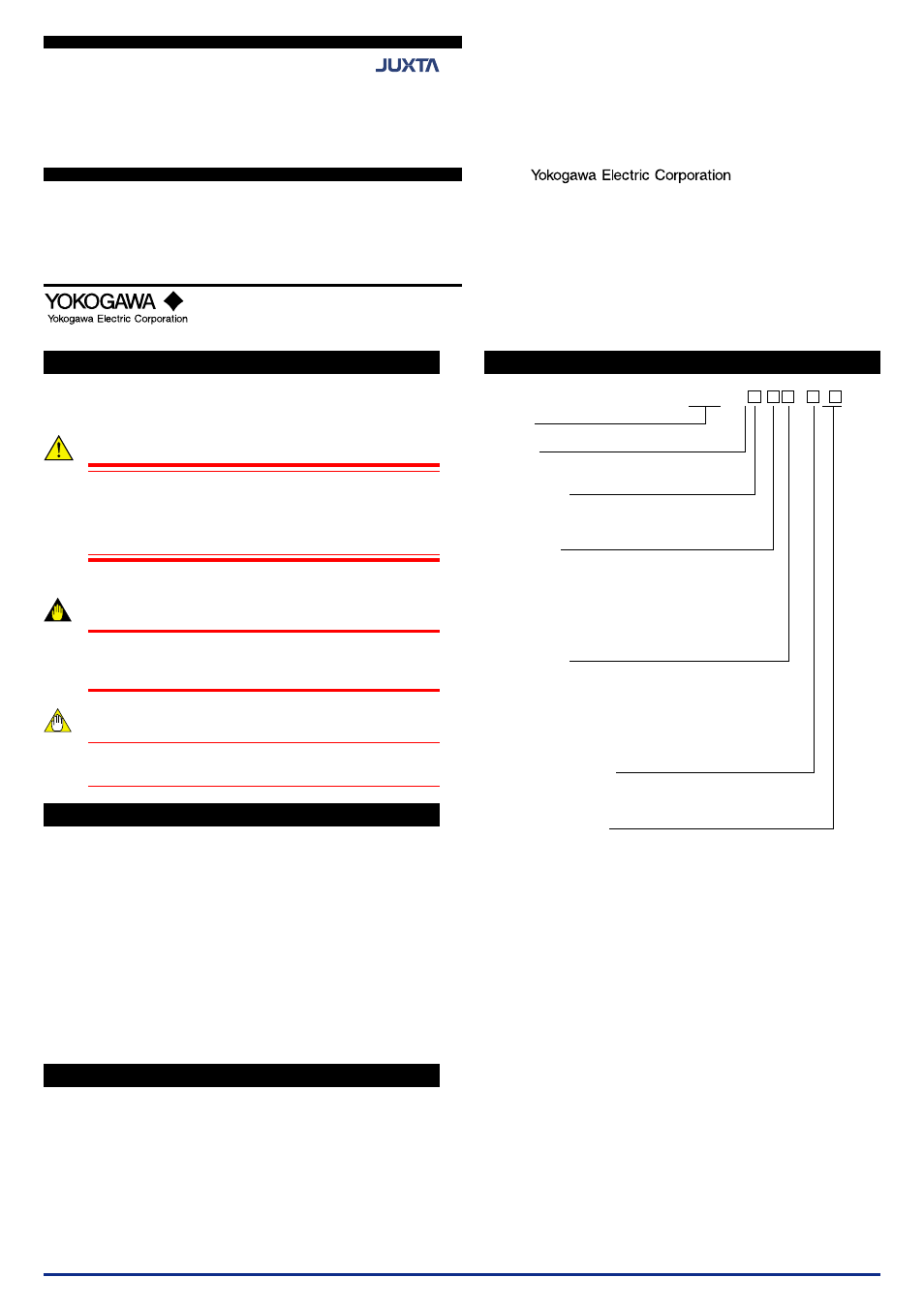
MODEL AND SUFFIX CODES
MH5 -01 - 0 /
Model
Output
1: 1 output
Power supply
1: 15-40V DC (Operating range: 12 to 48 V)
6: 100-240 V AC/DC (Operating range: 85 to 264 V)
Input signal
A:
−
20 to
+
20 mA DC (with 250
Ω
receiving resistor)
B:
−
50 to
+
50 mA DC (with 100
Ω
receiving resistor)
1:
−
10 to
+
10 V DC
2:
−
2 to
+
2 V DC
Z: (Custom order)
Customized current signals or voltage signals
Output signal
A: 0 to 20 mA DC
Span is 5 mA or more
B: 0 to 5 mA DC
Span is 1 mA or more
1:
−
10 to
+
10 V DC
Span is 0.1 V or more
2:
−
100 to
+
100 mV DC
Span is 10 mV or more
Z: (Custom order)
Customized current signals or voltage signals
Breakpoint linearization
0: Not available
1: Available
Optional specification
/SN: Without socket
/R100: With 100
Ω
receiving resistor
/R250: With 250
Ω
receiving resistor
IM 77J04H05-01E