Installation locations, External wiring, Part names of front panel – Yokogawa JUXTA MA7D User Manual
Page 2: Maintenance, 1 calibration apparatus, 2 calibration procedure, Warning, Important
2
IM 77J04A07-02E
2nd Edition June 01,2004-00
5. INSTALLATION LOCATIONS
●
Avoid the following environments for installation locations:
Areas with vibration, corrosive gases, dust, water, oil, solvents, di-
rect sunlight, radiation, a strong electric field, and/or a strong
magnetic field
●
If there is any risk of a surge being induced into the power line
and/or signal lines due to lightning or other factors, a dedicated
lightning arrester should be used as protection for both this unit
and a field-installed device.
6. EXTERNAL WIRING
WARNING
To avoid the risk of an electric shock, turn off the power
supply and use a tester or similar device to ensure that no
power is supplied to a cable to be connected, before carring
out wiring work.
Wiring should be connected to the terminals on the socket of the prod-
uct. The terminals for external connections are of M3.5 screws. Use
crimp-on terminal lugs for connections to the terminals.
●
Recommended cables: A nominal cross-sectional area of 0.5 mm
2
or thicker for signal cables, and that of 1.25 mm
2
or thicker for
power cables.
10 11
1
2
3
9
8
7
6
5
4
L+
N–
GND
1
2
+
–
10
11
+
–
9
7
8
4
5
6
PS+
COM
–
–
+
–
+
4
5
6
4
5
6
–
+
Output-2
Input
Output-1
Power supply
When using
internal
power supply
When using
external
power supply
Example to construct
Intrinsically Safe System
using Zener Barrier
IMPORTANT
●
The power line and input/output signal lines should be
installed away from noise-generating sources. Other
wise accuracy cannot be guaranteed.
●
The grounding resistance must be 100
Ω
(JIS Class D
grounding). The length and thickness of the grounding
cable should be as short and thick as possible. Directly
connect the lead from the ground terminal (terminal no.
9) of the product to the ground. Do not carry out daisy-
chained inter-ground terminal wiring.
●
Use of the product ignoring the specifications may
cause overheating or damage. Before turning on the
power, ensure the following:
(a) Power supply voltage and input signal value applied
to the product should meet the required
specifications.
(b) The external wiring to the terminals and wiring to
ground are as specifications.
●
Do not operate the product in the presence of
flammable or explosive gases or vapors. To do so is
highly dangerous.
●
The product is sensitive to static electricity; exercise
care in operating it. Before you operate the product,
touch a nearby metal part to discharge static electricity.
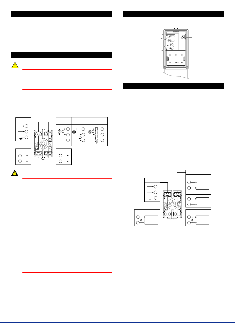
7. PART NAMES OF FRONT PANEL
The figure below shows the MA7D with its front panel (cover) being
open.
Output-1
Zero-adjustment volume
Span-adjustment volume
Output-2
Zero-adjustment volume
Span-adjustment volume
Power indicator lamp
Lit during power on
8. MAINTENANCE
The product starts running immediately when the power is turned on;
however, it needs 10 to 15 minutes of warm-up before it meets the
specified performance.
8.1
Calibration Apparatus
●
A DC voltage/current standard (Yokogawa 7651 or the equivalent)
●
A digital multimater (Yokogawa 7561 or the equivalent)
●
A precision resistor of 250
⍀
±
0.01%, 1 W
8.2
Calibration Procedure
(1) Connect the instruments as shown below. First adjust the output-1
signal and then the output-2 signal.
(2) Use the DC voltage/current standard and apply input signals
equivalent to 0, 25, 50, 75, and 100% of the input span to the
product. Check to see the corresponding output voltages are 0,
25, 50, 75, and 100% respectively and within the specified accu-
racy rating. “R” is used for current output.
●
If the output signals are out of the accuracy rating range, adjust
the output signal level using the zero and span adjustment vol-
umes on front face of the product.
10 11
1
2
3
9
8
7
6
5
4
9
7
8
1
2
R
10
11
R
4
5
5
6
R: 250
⍀
precision resistor
for current output
R: 250
⍀
precision resistor
for current output
Power supply
Output-2
Input
With SINK current
Without SINK current
Output-1
Ϫ
ϩ
Ϫ
ϩ
Ϫ
ϩ
L
ϩ
N
Ϫ
GND
DC voltge/
current
standard
DC voltge/
current
standard
Digital
multimater
Ϫ
ϩ
Digital
multimater