Installation locations, External wiring, Maintenance – Yokogawa JUXTA VJT6 User Manual
Page 2: Rjc sensor, Warning, Important, 1 calibration apparatus, 2 calibration procedure
2
IM 77J01T06-01E
4th Edition
Feb. 09,2007-00
5. INSTALLATION LOCATIONS
●
Avoid the following environments for installation locations:
Areas with vibration, corrosive gases, dust, water, oil, solvents, di-
rect sunlight, radiation, a strong electric field, and/or a strong
magnetic field
●
If there is any risk of a surge being induced into the power line
and/or signal lines due to lightning or other factors, a dedicated
lightning arrester should be used as protection for both this unit
and a field-installed device.
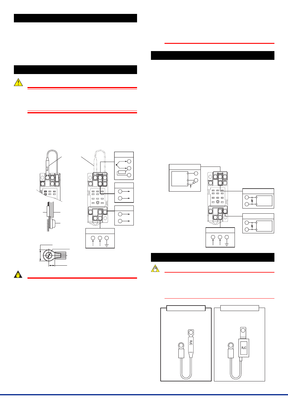
6. EXTERNAL WIRING
WARNING
To avoid the risk of an electric shock, turn off the power
supply and use a tester or similar device to ensure that no
power is supplied to a cable to be connected, before carring
out wiring work.
Wiring should be connected to the terminals on the socket of the prod-
uct. The terminals for external connections are of M3 screws. Use
crimp-on terminal lugs for connections to the terminals.
●
Recommended cables: A nominal cross-sectional area of 0.5 mm
2
or thicker for signal cables, and that of 1.25 mm
2
or thicker for
power cables.
10
11
3
2
1
4
5
6
7
8
9
Signal
line
RJC
sensor
Terminal
screw
10
11
3
2
1
4
5
6
7
8
9
11
10
8
L+
N–
GND
7
9
+
–
2
1
3
4
5
+
–
+
–
RJC
Power supply
RJC sensor
(A1167HT)
Output-2
Input signal
Output-1
Recommended crimp-on lug
size (Unit: mm)
5.5 or less
5.5 or more
ø3.2 to 3.5
IMPORTANT
●
Connect the RJC sensor at the correct position as shown
above. Otherwise temperatures cannot be measured
correctly.
●
Connect the RJC sensor so that it overlaps the input
signal line.
●
Handle the RJC sensor lead wire with care to prevent
disconnection.
●
The power line and input/output signal lines should be
installed away from noise-generating sources. Other
wise accuracy cannot be guaranteed.
●
The grounding resistance must be 100
Ω
(JIS Class D
grounding). The length and thickness of the grounding
cable should be as short and thick as possible. Directly
connect the lead from the ground terminal (terminal no.
8) of the product to the ground. Do not carry out daisy-
chained inter-ground terminal wiring.
●
Use of the product ignoring the specifications may cause
overheating or damage. Before turning on the power, en-
sure the following:
(a)Power supply voltage and input signal value applied to the
product should meet the required specifications.
(b)The external wiring to the terminals and wiring toground
are as specifications.
●
Do not operate the product in the presence of flammable
or explosive gases or vapors. To do so is highly danger-
ous.
●
The product is sensitive to static electricity; exercise
care in operating it. Before you operate the product,
touch a nearby metal part to discharge static electricity.
7. MAINTENANCE
The product starts running immediately when the power is turned on;
however, it needs 10 to 15 minutes of warm-up before it meets the
specified performance.
7.1
Calibration Apparatus
●
Calibrator (Yokogawa Meters & Instruments‘ CA71 or equivalent): 1
●
Temperature sensor (Yokogawa Meters & Instruments‘ B9108WA
or equivalent): 1
●
Digital multimater (Yokogawa 7561 or equivalent): 1
●
Precision resistor of 250
⍀
±
0.01%, 1 W
7.2
Calibration Procedure
(1) Connect the instruments as shown below. First adjust the output-1
signal and then the output-2 signal.
(2) Use the calibrator and apply input signals equivalent to 0, 25, 50,
75, and 100% of the input span to the product. Check to see the
corresponding output voltages are 0, 25, 50, 75, and 100% re-
spectively and within the specified accuracy rating. “R” is used for
current output.
●
If the output signals are out of the accuracy rating range, adjust
the output signal level using the zero and span adjustment vol-
umes on front face of the product.
10
11
3
2
1
4
5
6
7
8
9
11
10
8
Temperature sensor (B9108WA)
1
3
–
+
2
5
R
Ϫ
ϩ
7
9
R
Calibrator
R: 250
⍀
precision resistor
for current output
Power supply
Output-2
Input
Output-1
L
ϩ
N
Ϫ
GND
Digital
multimater
Ϫ
ϩ
Digital
multimater
8. RJC Sensor
NOTE
The product works normally when the RJC sensor
“A1167HT” (see the figures below) is connected to the
socket. If another RJC sensor is connected, it does not
work normally. Make sure that the correct RJC sensor is
connected referring to the figures below.
The RJC sensor for the product
(For the VJT6 with style of 3.00
or higher)
The RJC sensor for the VJT6 with
former style
“Not available for the VJT6 with
style of 3.00 or higher”
Part number: A1167HT
Part number: E9786WA
The style of VJT6 is indicated on the nameplate attached to the
side face of the main unit.