List of parameters, Maintenance, 1 calibration apparatus – Yokogawa JUXTA VJP8 User Manual
Page 4: 2 calibration procedure, Fig. 10.1
4
All Rights Reserved. Copyright © 1999, Yokogawa M&C Corporation
IM 77J01P08-01E
9.LIST OF PARAMETERS
No.
Item
Display
Remarks
No.
Item
Display
Remarks
01
Model
MODEL
02
Tag No.
TAG NO
03
Self-check result
SELF CHK
Display items
A
Display1
DISPLAY1
B
Display2
DISPLAY2
A01
Input value
INPUT1
B01
Input value
INPUT1
A33
Temporary memory 1
T1
B31
Integrating counter 1
COUNTER1
A34
Temporary memory 2
T2
B32
Integrating counter 2
COUNTER2
A54
Temporary memory 3
T3
B33
Integrating counter 3
COUNTER3
A55
Temporary memory 4
T4
B34
Integrating counter 4
COUNTER4
A54
Status
STATUS
*1
B60
Self-check result
SELF CHK
A56
Rev. no
REV NO
A58
MENU REV
MENU REV
A60
Self-check
SELF CHK
*1 The Status is displayed for service personnel to see history records.
Setting items
D
Setting (I/O)
SET(I/O)
F
Setting (communication)
SET (COM)
D01
Tag no. 1
TAG NO.1
F01
Communication protocol
PROTOCOL
D02
Tag no. 2
TAG NO.2
F02
Address
ADDRESS
D03
Comment 1
COMMENT1
F03
Baud rate
BAUD RATE
D04
Comment 2
COMMENT2
F04
Parity
PARITY
D10
Range unit
UNIT
F05
Data length
DATA LEN
D41
Pulse rate range
PULSE RATE
F06
Stop bit
STOP BIT
D42
Pulse width type
PULSE TYPE
F07
Decimal point position of input
INPUT DEC PT
D43
Pulse width time
PULSE TIME
F60
Self-check result
SELF CHK
D50
Input filter
INPUT FILTER
D60
Self-check result
SELF CHK
Adjusting items
There are items not displayed depending on what output-2 is specified.
P
Adjustment
ADJUST1
P60
Self-check result
SELF CHECK
10.MAINTENANCE
The product starts running immediately when the power is turned on;
however, it needs 10 to 15 minutes of warm-up before it meets the
specified performance.
For cleaning the instrument, use a soft and dry cloth.
10.1 Calibration Apparatus
Pulse generator (Yokogawa FG100 or the equivalent): 1
A counter(Yokogawa TC100 or the equivalent) or oscilloscope
(Yokogawa DL1540 or the equivalent): 1
A precision resistor (1k
⍀, 1.6 k⍀): 1 each
6V battery: 1
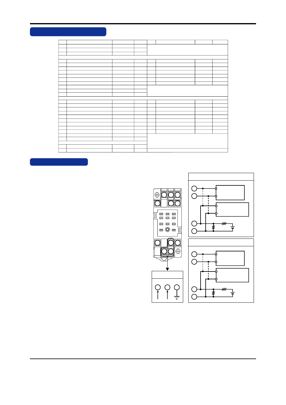
10.2 Calibration Procedure
Connect the instruments as shown in Fig.10.1. First adjust the out-
put-1 signal and then the output-2 signal.
Produce a rectangular pulse of any frequency from the pulse genera-
tor to measure the value using a counter or oscilloscope. (Connect the
counter or oscilloscope as the broken line shown in figure 10.1.)
Next, connect the counter to the terminals 7 and 9, or terminals 2 and
5, then check that the frequency (input frequency x set rate) is output.
When using a oscilloscope, the wave shaping of output pulse can be
confirmed.
10
11
3
2
1
4
5
6
7
8
9
11
10
8
L+
N-
GND
9
7
Calibration for output-1
Calibration for output-2
4
3
1.6k
Ω
1k
Ω
6V
Battery
6V
Battery
+
-
+
-
5
2
4
3
1.6k
Ω
1k
Ω
+
-
+
-
Power supply
Pulse
Generator
Counter or
Osilloscope
Pulse
Generator
Counter or
Osilloscope
Fig. 10.1