Yokogawa SC4A 19mm Conductivity Sensors User Manual
Page 8
IM 12D7J4-E-E
6
2. INSTALLATION
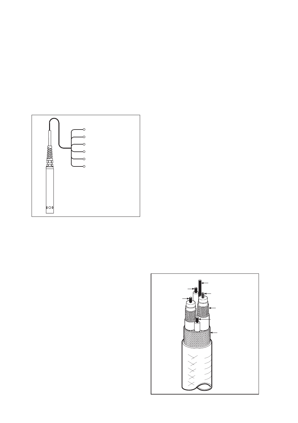
2-1. Connection
The cable is six wire multicore and covered
with a thermoplastic TPE. The wires are also
covered with thermoplastic TPE individually
and coloured. The cable connections
are supplied with 2 mm terminations for
connection to the transmitter, or connection
box: these pins quarantee a correct and
simple connection to the terminals.
Figure 2-0. Sensor Wiring
At the instrument end the cable termination
tags are numbered to correspond with their
respective terminals of the transmitters.
NOTE:
If the cable is used with a connection box,
type BA10 then special purpose cable, type
WF10 must be used between connection
box and transmitter connected to the same
terminals as the cell cable. A maximum of
50 metres total cable length is permissable.
2-2. Mounting
The mounting is by a compression gland or
sanitary adapter, giving a simple effective
method of direct insertion in process
pipework. For mounting the retractable
sensor refer to the instruction manual of the
PR4A retractable holder. Before mounting
a cell in a process plant environment the
following points should be considered:
s
s
e
c
o
r
p
f
o
w
o
lf
,
e
v
it
a
t
n
e
s
e
r
p
e
r
,
d
o
o
g
a
-
liquid through the cell should exist. Hence,
the cell must be mounted in the process
Figure 2-1. WF10 Cable
overall
shield
screen
B
E
A
C
D
in such a way that the flow through it
represents the true composition of the
liquid. The flow through the cell should be
uninterrupted and the cell should not be
mounted at a “dead” angle.
s
s
e
c
o
r
p
e
h
t
n
i
d
e
s
r
e
m
m
i
e
b
t
s
u
m
l
l
e
c
a
-
liquid to a level above the outlet to ensure
an uninterrupted liquid path between the
electrodes.
y
a
w
a
h
c
u
s
n
i
d
e
t
n
u
o
m
e
b
d
l
u
o
h
s
l
l
e
c
e
h
t
-
to allow easy removal for
maintenance. It is recommended that
the cell is mounted in a ‘by-pass’ directly
behind a drain valve.
2-3. Safety warning
For SC4A..AD to avoid the sensor
shooting out, never install in application
where pressure can exceed specified
maximum. Never loosen mounting nut while
system is pressurised.
2-4. Commisioning
The sensor cable is marked with a label
specifying complete MS mode, Serialnumber
and calibrated cell constant*. This cell
constant must be entered in the EXA
transmitter to achive an accurate
measurement.
* Always specify complete MS code
and serialnumber in communication with
Yokogawa organisation with regards to
performance issues or warranty matters.
11 Temperature
12 Temperature
13 Outer electrode
14 Outer electrode
15 Inner electrode
16 inner electrode