3 wiring, 4 model and suffix codes, 3 connector materials – Yokogawa SC25F User Manual
Page 2: 4 electrical specifications, 5 operational specifications, 6 dimensional drawing, 7 cable installation, 1 definition connector pin to cable, 2 connection cable to flxa analyzer
IM 12B6W2-03E-E
Subject to change without notice
Printed in The Netherlands, 01-1111 I
Copyright©
IM 12X0X0-E-E
Subject to change without notice
Printed in The Netherlands, 00-000 (A) I
Copyright ©
Yokogawa has an extensive sales and
distribution network.
Please refer to the European website
(www.yokogawa.com/eu) to contact your
nearest representative.
YOKOGAWA EUROPE BV
Euroweg 2
3825 HD AMERSFOORT
The Netherlands
www.yokogawa.com/eu
YOKOGAWA ELECTRIC CORPORATION
World Headquarters
9-32, Nakacho 2-chome, Musashino-shi
Tokyo 180-8750
Japan
www.yokogawa.com
YOKOGAWA CORPORATION OF AMERICA
2 Dart Road
Newnan GA 30265
USA
www.yokogawa.com/us
YOKOGAWA ELECTRIC ASIA Pte. LTD.
5 Bedok South Road
Singapore 469270
Singapore
www.yokogawa.com/sg
YOKOGAWA CHINA CO. LTD.
3F Tower D Cartelo Crocodile Building
No.568 West Tianshan Road Changing District
Shanghai, China
www.yokogawa.com/cn
YOKOGAWA MIDDLE EAST B.S.C.(c)
P.O. Box 10070, Manama
Building 577, Road 2516, Busaiteen 225
Muharraq, Bahrain
www.yokogawa.com/bh
2.3 Connector materials
Housing
: Polybutylene terephthalate
UL94V-0, color: black.
O-ring
: Nitrilbutadieenrubber,
color: black.
Nut
: Brass.
Contact finishing
: Gold plated.
2.4 Electrical specifications
Twisted pair cables : Capacity < 50 pF/m
Resistance < 100 Ω/km
Characteristic Impedance 120 Ω
Connector
: Maximum rated current 5 A
Maximum voltage 125 V
2.5 Operational specifications
Temperature
: -40 ~ +85 °C (-40 ~ +185 ºF)
Water Proof
: IP67 (conform IEC60529)
2.6 Dimensional drawing
Figure 1. Cable, available in four fixed lengths (L).
Length (L)
: 3, 5, 10, 20 m
(9.8, 16.4, 32.8, 65.6 ft)
Dia. connector (D) : 10.6 ± 0.2 mm
(4.17 ± 0.08 inch)
Dia. cable (d)
: 5.8 ± 0.1 mm
(2.28 ± 0.04 inch)
Wire pins
: 8 x 1.3 mm
(3.1 x 0.5 inch)
2.7 Cable installation
Procuring a smooth bend radius allows the cable
to absorb the impact of bending and thereby
increasing its life cycle. Minimum bend radius is
approx. 5 cm (2”).
When using cable ties, do not pinch or deform the
cable.
When connected cable is subjected to any motion
between two points, stress on the cable can be
prevented by an adequate cable length or using a
cable loop.
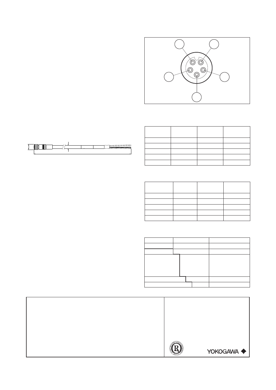
3 Wiring
Figure 2. Front view cable connector
3.1 Definition connector pin to cable
Pin #
Twisted
Wire
Wire
pair #
color
number
1
1 yellow 83
2
1 green 84
3
2 brown 87
4
drain black 82
5
2 white 86
3.2 Connection cable to FLXA analyzer
Signal Wire Wire FLXA
Description color number terminal
Supply +
brown
87
87
Supply Gnd
white
86
86
Data +
green
84
84
Data -
yellow
83
83
Shield black 82 82
4 Model and Suffix Codes
Model Suffix
Description
WU11
Conn. type -M9
M9 connector
Cable length
-03
3 m (9.8 ft)
-05
5 m (16.4 ft)
-10
10 m (32.8 ft)
-20
20 m (65.6 ft)
Cable finishing
-WP
Wire pins
Jacket material
-V
PVC
MODEL CODE
Serial #
D
d
L
2
1
5
4
3