En g l is h english – Pfister 0T8-410A User Manual
Page 3
E
N
G
L
IS
H
ENGLISH
ENGLISH
5
6
7
8
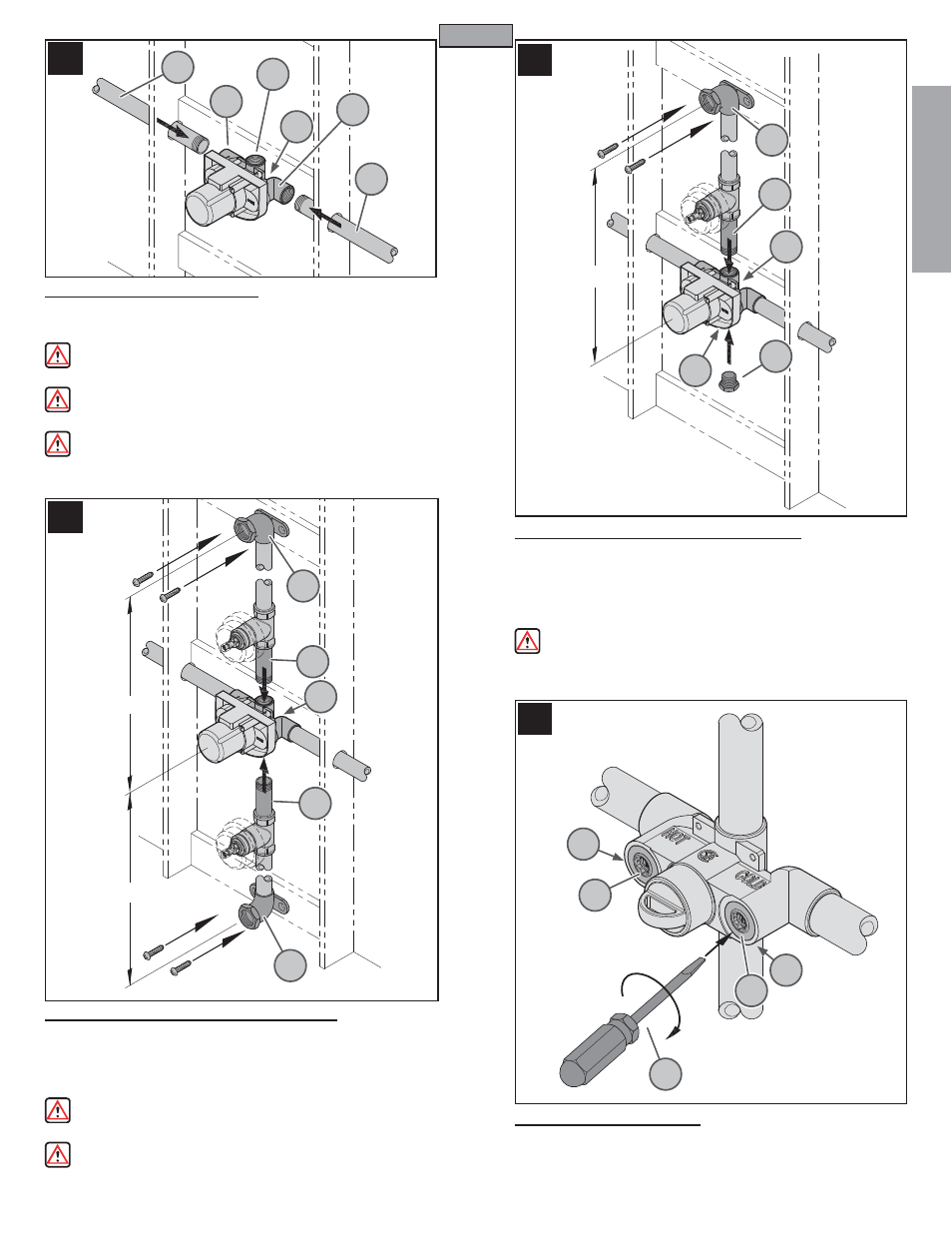
5 PIPE SUPPLY CONNECTIONS
Valve Body Inlets (5B) and Outlets (5C) are designed to accommodate 3/4-14
NPT pipe. Connect hot (5D) and cold (5E) water inlets to Valve Body (5A).
Pipe Unions or Couplings may be required (not included).
WARNING: For Iron Pipe Connections or threaded fi ttings, use thread
sealant or PTFE Plumber’s tape according to manufacturer’s instructions.
CAUTION: If using iron pipes, it is not recommended to reduce outlet
pipe diameter.
CAUTION: For Copper Sweat joints, it is important to remove Valve
Cartridge and other Plastic Components from the Valve Body before soldering.
Use copper pipe adapters (not furnished) in this type of installation.
6 TUB & SHOWER OUTLET CONNECTIONS
Connect Shower (6A) and Tub (6B) Outlet Pipes to Valve Body (6C). Connect
Pipe Elbows (6D) (not included) to ends of both pipes. We recommend using
drop elbows (6D) (not included). Securely fasten to framing or other solid
support. The height for outlet pipes is measured from the center of pipe elbow
to center of the valve body, as shown.
WARNING: For Iron Pipe Connections or threaded fi ttings, use thread
sealant or PTFE Plumber’s tape according to manufacturer’s instructions.
WARNING: Use only 3/4” Iron or Copper Pipe between valve and tub
spout (No PEX)! Do not reduce the inner pipe diameter!
7 SHOWER ONLY OUTLET CONNECTIONS
Connect Shower Outlet Pipe (7A) to Valve Body (7B). Plug Bottom Outlet
(7C) with Pipe Cap or Plug (7D). Connect Pipe Elbow (7E) (not included) to
end of the pipe. For copper pipe outlets, we recommend using drop elbows
(7E) (not included). Securely fasten to framing or other solid support. The
height for the outlet pipe is measured from center of pipe elbow to center of
valve body, as shown.
WARNING: For Iron Pipe Connections or threaded fi ttings, use thread
sealant or PTFE Plumber’s tape according to manufacturer’s instructions.
8 INTEGRAL VALVE STOPS
Integral Stops (8A) provide an alternate means to shut off the water supply. With
a fl at head screwdriver (8B), the water supply can be shut off by rotating the valve
stem (8C) clockwise. The integral stops can be used for temporary shutting off
the water supply to allow access to the cartridge assembly for maintenance.
3
5A
7B
7C
5B
5D
7A
7D
7E
5E
6A
6B
6D
6D
5C
6C
HOT
COLD
5B
8A
8A
8C
8C
8B
48"
8"Min
30" Min