En g li sh – Pfister R15-407K User Manual
Page 2
EN
G
LI
SH
ENGLISH
3
5
6
4
Thank you for purchasing this Price Pfister product. All Price Pfister products
are carefully engineered, and factory tested to provide long trouble-free use
under normal conditions. This product is easy to install using basic tools
and our easy to follow illustrated instructions. If you have any questions
regarding this product, call 1-800-Pfaucet (1-800-732-8238).
1 BEFORE PROCEEDING
WARNING: Read all the instructions completely before proceeding.
Price Pfister recommends calling a professional if you are uncertain
about installing this product!
This product has been designed for use with the Price Pfister 0X6-
140R or JX6-140R Roman Tub series rough-in. It will not work with any
other product.
This product should be installed in accordance with all local and state plumbing
and building codes. For optimum performance of your new Price Pfister faucet,
a minimum water pressure of 25 PSI (172 kPa) is recommended.
Your installation will require supply tubes. To preserve the high flow characteristics
of these valves, it is necessary to use ½” I.D. (⅝” O.D.) copper tubing or Price
Pfister Quick Connect Hose Kit 15-136. Consult the store where you purchased
your faucet for the recommended connections that you may require for your area.
Before installing your Diverter Valve, Price Pfister recommends installation of
a ½” shock arrester before each supply valve. If deck thickness exceeds 1-¾”
Price Pfister Stem Extension Kit 974-370 must be used.
2 SHUT OFF WATER SUPPLY
Locate water supply inlets and shut off the water supply valves. These are
usually found near the water meter. If you are replacing an existing faucet,
remove the faucet from the tub and clean the tub surface thoroughly.
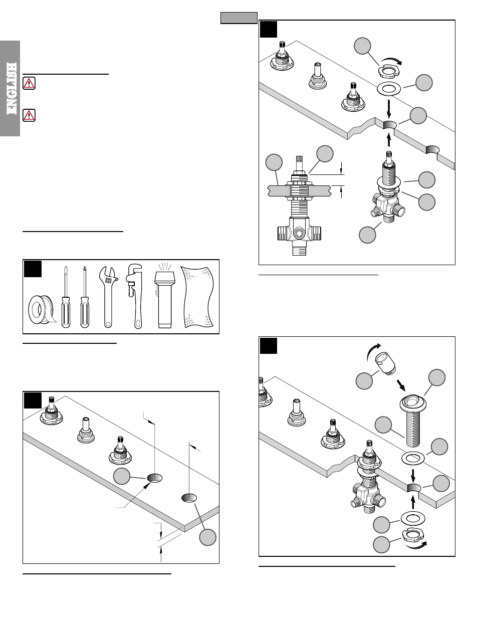
3 TOOLS RECOMMENDED:
For Iron Pipe Installation:
● PTFE Plumber’s Tape ● Slotted screwdriver
● Phillips Screwdriver
● Adjustable wrench
● Pipe Wrench
● Flashlight
● Cloth
For soldered copper and non-standared installations, some additional tools
may be required.
4 RECOMENDED COMPONENT LOCATIONS
Maximum distance between Diverter Valve (4A) and Spray Head Holder (4B)
is not to exceed 16” (406 mm). Note: Recommended all holes to be 1-¼”
(32 mm) diameter.
5 DIVERTER VALVE INSTALLATION
Remove upper Locknut (5A) and Washer (5B) from Diverter Valve Body (5C).
From underneath deck, insert Diverter Valve Body (5C) through deck hole
(5D) and adjust lower Locknut (5E) and Washer (5F) so that top of Diverter
Shank (5G) is ½” (13 mm) above Mounting Surface (5H). From above deck,
place Locknut (5A) and Washer (5B) onto Diverter Shank (5G) and wrench
tighten until Diverter Valve Body (5C) is firmly secured to deck.
6 SPRAY BASE HOLDER INSTALLATION
Connect Spray Holder (6A) onto Spray Base (6B). Insert Spray Base (6B) trough
Washer (6C) and into Deck Hole (6D). From underneath deck, place Washer
(6E) onto Spray Base Shank (6F) and tighten with Locknut (6G). Be sure Spray
Holder (6A) is centered and facing forward before final tightening.
2
5A
4A
4B
16” (406 mm) MAX.
1-1/4” (32 mm) DIA.
1-3/4” (45 mm) MAX.
1/2” (13 mm)
5G
5H
5F
5E
5B
5D
5C
6A
6F
6C
6D
6E
6G
6B