En g l is h english – Pfister R89-7CBY User Manual
Page 3
E
N
G
L
IS
H
ENGLISH
ENGLISH
8
7
9
10
11
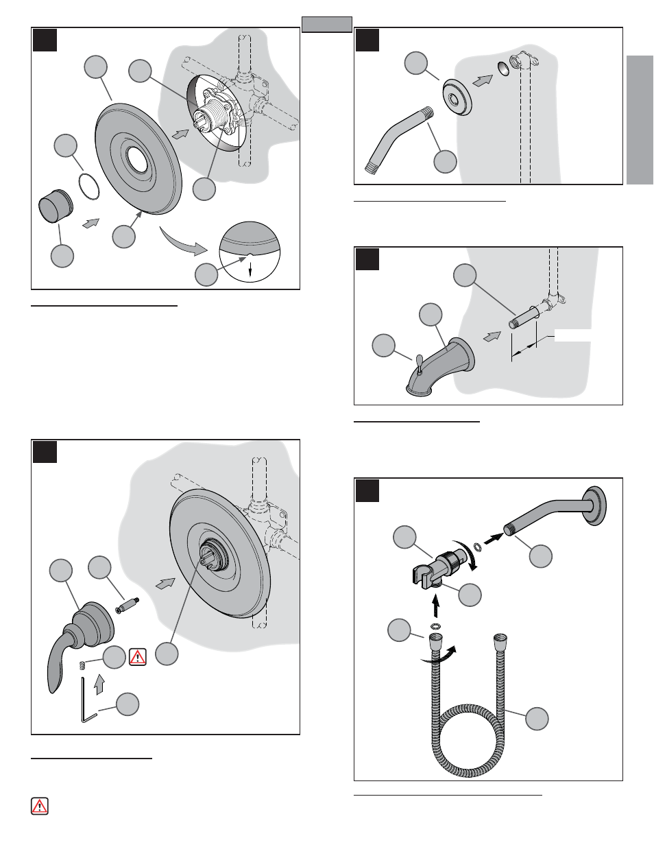
7 TRIM FLANGE ATTACHMENT
Position Flange (7A) on Valve (7B) with Drain Hole (7C) at the bottom. Place
Protective Washer (7D) on the short end of the reversible Retainer Sleeve (7E).
Screw Retainer Sleeve (7E) onto threaded section of the Stem and Bonnet (7G).
Tighten Retainer Sleeve (7E) by hand until Flange (7A) is snug to fi nished wall
surface. If the short end of the Retainer Sleeve (7E) is too short, reverse it to
use the longer end.
10 SPOUT INSTALLATION
Apply PTFE plumbers tape on both ends of Pipe Niple (10A) (not included).
Screw Pipe Niple (10A) into the elbow inside the wall and tighten with pipe
wrench. The Pipe Niple (10A) is to project 3
7
/
8
" to 4" from the fi nished wall.
Screw Tub Spout (10B) onto Pipe Niple (10A) and tighten until Spout is properly
positioned and fl ush to the fi nished wall.
9 SHOWER ARM INSTALLATION
Insert the end of Shower Arm (9A) through the Shower Flange (9B). Apply PTFE
plumber's tape to back end of Shower Arm (9A) according to manufacturer's
instructions. Screw the end of Shower Arm (9A) into pipe elbow inside the wall.
Slide Shower Flange (9B) tight to the wall.
11 ARM MOUNT & HOSE INSTALLATION
Screw Arm Mount (11A) into the end of Shower Arm (11B). Connect Hose (11C) into
the Arm Mount Outlet (11D) by turning Metal Hose Fitting (11E).
8 HANDLE ATTACHMENT
Screw Stem Extender (8A) onto the Valve Stem (8B). Thread the Set Screw (8C)
into the Handle (8D) and thread it in only three to four turns. Place Handle (8D)
onto the Stem Extender (8A) and tighten the Set Screw (8C) by using the Hex
Wrench (8E) that is provided.
Make sure Set Screw (8C) is securely tightened to handle (8D).
3
7A
9A
7B
7C
7C
7D
7E
7G
9B
10A
3
7
/8” to 4”
10B
10C
8A
8B
8C
8D
8E
11A
11B
11C
11D
11E