English – Pfister 0X8-310A User Manual
Page 4
9
10
12
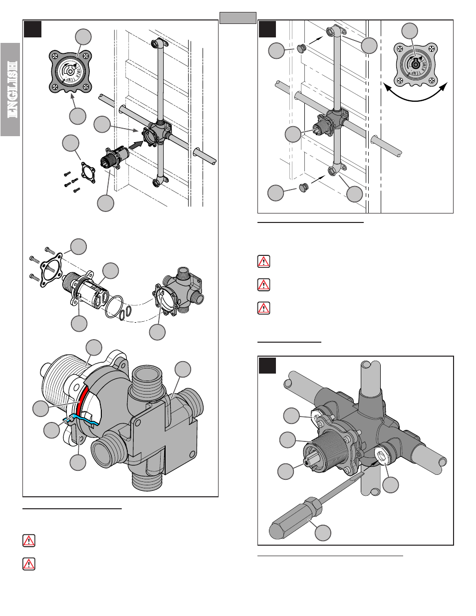
9 CARTRIDGE REASSEMBLY
Once all pipe joints are soldered, reassemble the Cartridge Assembly (9A)
and Backup Plate (9B) into Valve Body (9C). Be sure that Notch (9D) from
the Bonnet (9E) is pointing down (For back-to-back installation see step 20).
WARNING: When reassembling unit, be sure that Tabs (9F) from the
Cartridge Assembly (9A) are set properly on the Valve Body groves (9G).
WARNING: When reassembling the Cartridge Assembly (9A) and Backup
Plate (9B), be certain that the placement of the O-ring (9H) is within the groove
and not pinched between the backup flange (9G) and casting wall (9J). Failure
to do so will result in water leaks and water damage.
10 PRESSURE TESTING VALVE
Use two
1
/
2
" iron pipe plugs (10A) (not included) on both Shower Outlet (10B)
and Tub Outlet (10C). Turn Stem (10D) counterclockwise to full on position
and check all connections for leaks. Rotate Stem (10D) clockwise to turn off.
Look for leaks from the outlets.
WARNING: Pressure testing is not to exceed 250 PSI. Make sure
pressure is balanced between hot and cold inlets.
WARNING: Differential pressure of hot and cold inlets must not exceed
100 PSI.
CAUTION: Slowly remove pipe plugs (10A) from tub and shower outlets
to relieve pressure.
11 UNIT START UP
Turn on water supplies, and check all connections for leaks.
12 MODEL WITH INTEGRAL VALVE STOPS
Integral Stops (12A) provide an alternate means to shut off the water supply. With
a flat head screwdriver (12B), the entire water supply can be shut off by rotating
the valve stem (12C) clockwise. The integral stops can be used for temporary
shutting off the water supply to allow access to the cartridge assembly (12D) for
maintenance.
4
ENGLISH
ENGLISH
9D
9B
9A
9C
9A
9E
9G
9F
9A
9B
9H
9G
9J
ON
OFF
10A
10A
10C
10B
10D
10D
12A
12A
12B
12C
12D
9C