English, Installation – Pfister 0X8-310A User Manual
Page 2
4
3
5
Thank you for purchasing this Price Pfister product. All Price Pfister products are carefully engineered, and factory tested to
provide long trouble-free use under normal conditions. This valve is easy to install using basic tools and our easy to follow
illustrated instructions. If you have any questions regarding this product, call 1-800-Pfaucet (1-800-732-8238)
.
1 BEFORE PROCEEDING:
WARNING: Read all the instructions completely before proceeding. Price
Pfister recommends calling a professional if you are uncertain about installing
this product!
This product should be installed in accordance with all local and state plumbing
and building codes.
Use only
1
z
2
” Iron or Copper Pipe between valve and tub spout (No PEX)!
2 WATER SHUT-OFF:
Locate water supply inlets and shut off water supply valves. These are usually
found near water meter.
SURFACE PREPARATION:
For optimum performance of your new Price Pfister Single Control Pressure
Balancing Valve, a minimum water pressure of 20 PSI is required. Have the
basic tools ready for removal of old valve. If you are replacing an existing Valve,
disconnect the old valve and clean the mounting surface thoroughly. Align and
adjust water supply pipes to recommended dimensions. For new construction,
Install water supply pipes to recommended dimensions.
3 TOOLS RECOMMENDED:
For Iron Pipe Installation:
● PTFE Plumber’s Tape or Thread Sealant
● Slotted screwdriver
● Phillips Screwdriver
● Adjustable wrench
● Pipe Wrench
● Flashlight
● Cloth
For soldered copper and non-standard installations, some additional tools may
be required.
INSTALLATION
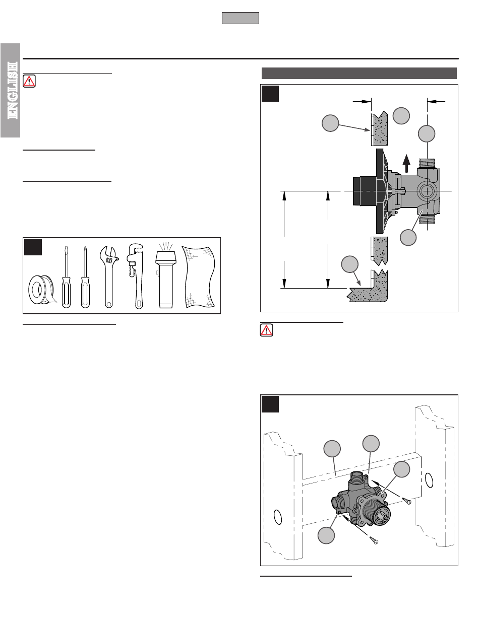
4 VALVE INSTALLATION
CAUTION: Be sure to position Valve Body (4A) correctly in wall, ”SHWR”
marking up.
Depth (4B) for valve body in wall is measured from center of shower outlet (4D)
to finished wall surface (4C). Minimum distance (4B) is 2
5
/
8
" and maximum
is 3
1
/
2
". Height is measured from bottom of floor (4E) to center of valve body
(30" for Tub & Shower and 48" for Shower only).
5 SECURING VALVE BODY
3
/
16
” Dia. Screw holes (5B) are provided to secure Valve Body (5A) to framing
(5C) or other solid support. For special direct mount (Thin Wall Installation) go
to step 18. For PEX installation, connect PEX lines prior to securing.
2
ENGLISH
ENGLISH
4C
4D
4B
SHWR
FLOOR
48”
SHOWER
ONLY
30”
TUB &
SHOWER
2
5
/
8
” - 3
1
/
2
”
FINISHED
WALL
4E
5B
5C
5B
4A
5A