English, Faucet installation, Maintenance & care – Pfister GT49-DF1K User Manual
Page 2
ENGLISH
ENGLISH
3
2
FAUCET INSTALLATION
4
5
6
8
7
9
MAINTENANCE & CARE
Thank you for purchasing this Price Pfister product. All Price Pfister products are carefully engineered, and factory tested to
provide long trouble-free use under normal conditions. This product is easy to install using basic tools and our easy to follow
illustrated instructions. If you have any questions regarding this product, call 1-800-Pfaucet (1-800-732-8238).
1 BEFORE PROCEEDING
WARNING: Read all the instructions completely before proceeding. Price Pfister
recommends calling a professional if you are uncertain about installing this product!
This product should be installed in accordance with all local and state plumbing and
building codes.
This product has been designed for use with the Price Pfister 0W8-01 Wallmout
Valve Body. It will not work with any other product.
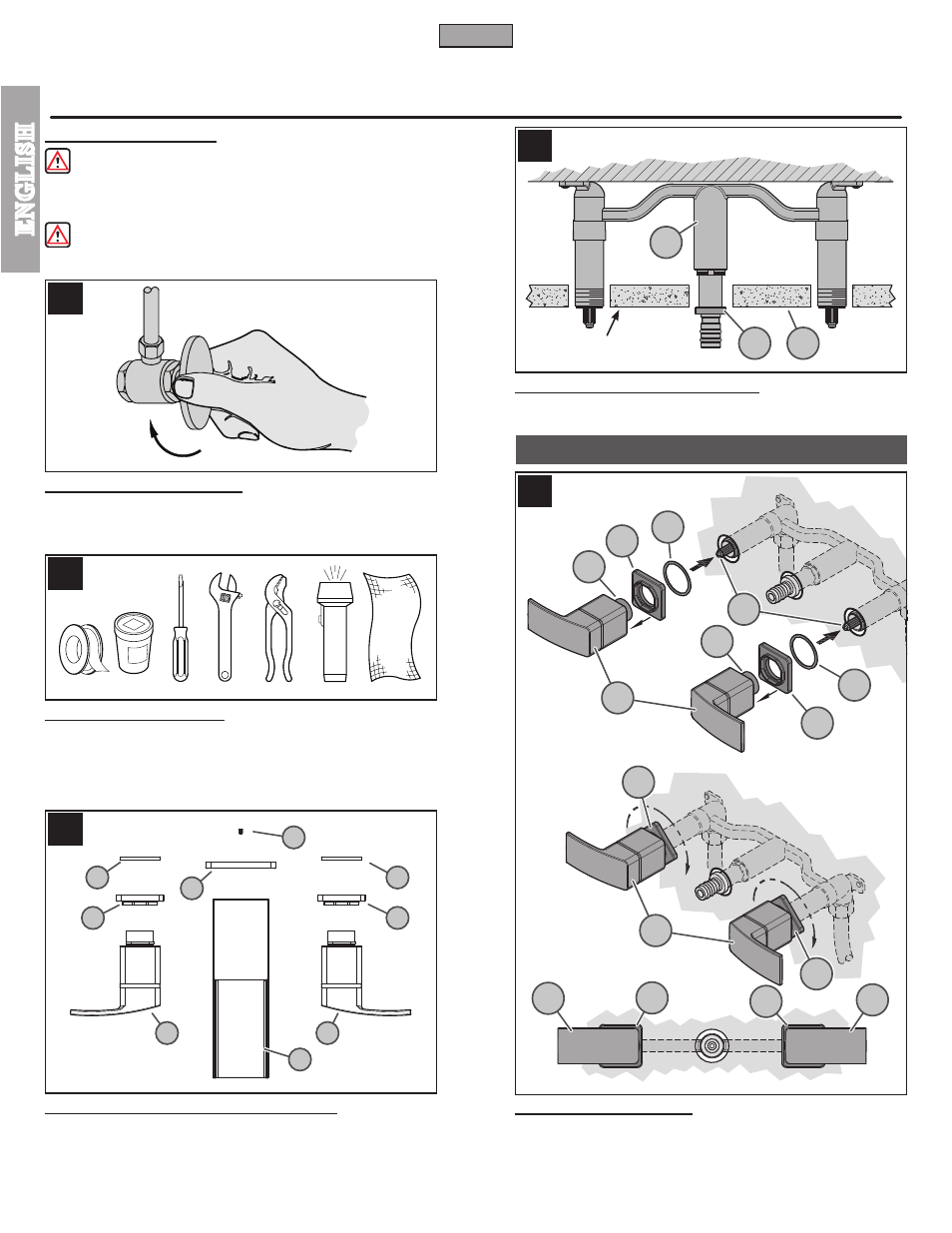
2 SHUT OFF WATER SUPPLY
Locate water supply inlets and shut off the water supply valves. These are usually found
under the sink or near the water meter. If you are replacing an existing faucet, remove
the old faucet from the sink and clean the sink surface thoroughly.
3 TOOLS RECOMMENDED
• PTFE Plumber's Tape
• Plumber's putty
• Slotted screwdriver
• Adjustable wrench
• Pliers
• Flashlight
• Cloth
Your installation may require new supply lines and / or shut-off valves or other additional
tools.
4 CHECKING THE CONTENTS OF THE BOX
Upon opening the box, check to ensure that all of the following items are included.
A Spout Body
B Handles (2x)
C Spout Flange
D Set Screw
E Valve Flange (2x)
F Seal Base (2x)
If any of these items are missing, please contact Price Pfister Consumer Service at
1-800-Pfaucet (1-800-732-8238).
5 VARIFING VALVE BODY POSITION
Verify that Valve Body (5A) is correctly positioned in wall. Be sure that Spout Adapter
Shoulder (5B) sits flush to finished wall surface (5C) as shown.
6 HANDLE INSTALLATION
Place Valve Flange (6A) onto Handle Sleeve (6B). Place Seal Base (6C) on back of
Valve Flange (6A). With Valves in “Closed” position, insert Handle Sleeve (6B) onto
Valve Stems (6D). Secure Handles (6E) by rotating Valve Flange (6A) clockwise untill
they sit snug and flush to finished wall surface. Be sure that Valve Flange (6A) and
Handles (6E) are horizontaly aligned. To remove Handles, reverse steps.
2
A
D
C
B
E
F
B
E
F
6A
6A
6E
6A
6E
6A
6A
6B
6B
6A
7A
7A
7D
7C
7A
7B
6C
5A
5C
5B
6C
OPEN
HOT
COLD
OPEN
FINISHED WALL
6D
7C
6E
6E