English – Pfister GT531-YPK User Manual
Page 3
ENGLISH
ENGLISH
7
8
9
10
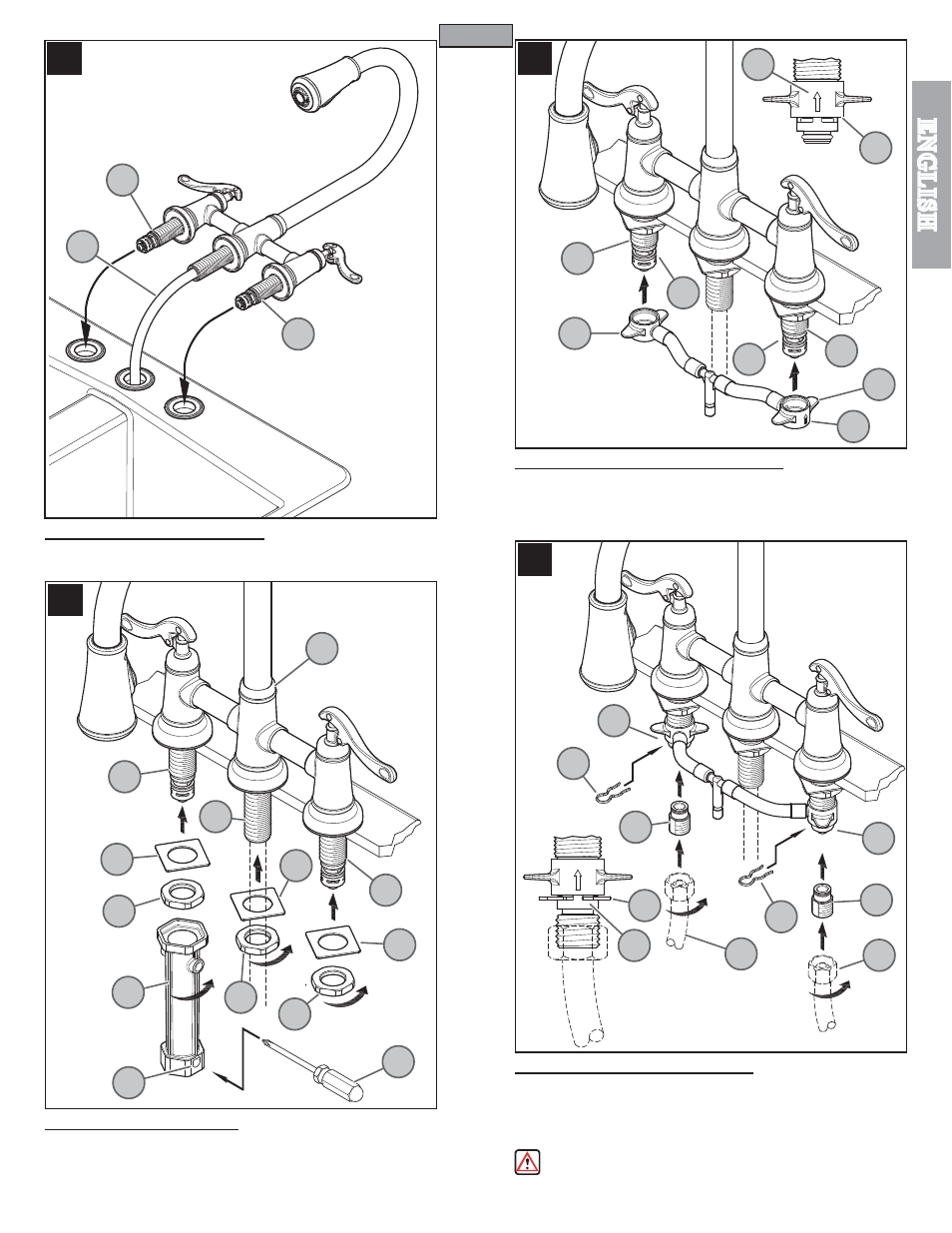
7 FAUCET BODY INSTALLATION
Insert the faucet Pull-out Hose (7A) through the center hole of the sink. Insert Valve
Shanks (7B) through the end holes of the sink.
8 SECURING FAUCET BODY
From underneath sink, place Square Washers (8A) onto Spout Shank (8B) and Valve
Shanks (8C). Tighten Locknuts (8D) by using Installation Tool (8E). For better leverage,
use a Screwdriver (8F), insert it through Hole (8G) and tighten the Locknuts (8D) until
Faucet Body (8H) is firmly secured to sink.
9 HOSE CONNECTION TO VALVE BODY
Slide the End Connectors (9A) with arrow (9D) pointing up onto the Valve Bodies (9B).
Push the End Connectors (9A) all the way up until completely seated. Be careful not
to damage O-Rings (9C).
Reverse steps to remove Hose Connection.
10 WATER SUPPLY CONNECTIONS
First, thread Inlet Connectors (10A) into Water Supply Lines (10B). Then, insert Inlet
Connectors (10A) into Valve Bodies (10C).
Hot water supply lines go into left inlet.
Cold water supply lines go into right inlet. (Supply lines not included). Please follow
manufacturer’s instructions when installing supply lines. Next, insert Clips (10D) into
Valve Body Holes (10E), to secure unit.
WARNING: Do not twist Inlet Connectors (10A) once installed!
Reverse steps to remove.
3
HOT
COLD
7A
7B
7B
8A
8D
8E
8H
8F
8G
8A
8D
8D
8A
8C
8B
8C
10A
10A
10C
10C
10B
10B
10D
10E
10D
10D
9A
9C
9C
9A
9A
9D
9D
9B
9B