0 functional description en – Nilfisk-ALTO Contractor Diesel User Manual
Page 6
41
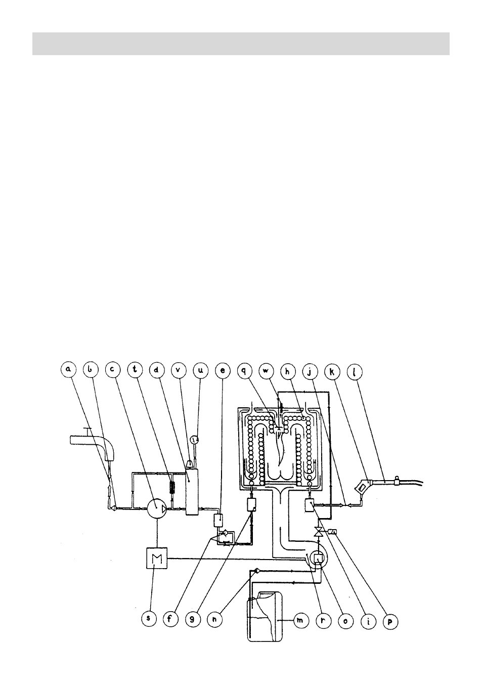
a Inlet quick-connector
b Water filter
c
High pressure pump
d Unloader/regulator (recycling valve)
e Flow switch
f
Throttle valve
g Flow switch
h Burner coil
i
Temperature sensor
j
Outlet quick-connector
k
Spray handle
I
Double spray lance
m Fuel tank ”Jerry-can”
n Burner fuel filter
o Fuel pump
p Magnetic solenoid valve
q Fuel nozzle
r
Blower for burner
s Diesel engine
t
Safety valve (internal)
u Pressure gauge
v Water volume adjustment
w Flame sensor
7.0 Functional description
EN
The water passes from the inlet connector (a)
through a water filter (b) and into the high pres-
sure pump (c). The high pressure water is
passed through the regulating unloader
(recycling valve) (d) and the first flow control
(e) to the throttle valve (f) and through the
second flow control (g) into the burner-coil (h).
Here the water is heated to the required
temperature. At the outlet of the burner-coil the
hot high pressure water passes the tempera-
ture sensor (i) and proceeds through the outlet
connector (j) to the spray handle (k) and double
spray lance (1.) The fuel is drawn from the fuel
tank (m) through the fuel filter (n) by the fuel
pump (a). The fuel pump passes the fuel
through the magnetic solenoid valve (p) to the
fuel nozzle (q) where it is ignited. The
combustion in the burner is monitored by the
flame sensor (w) and is supplied with air from
the fan (r), which together with the high pres-
sure pump (c) are driven by the diesel engine
(s).