Troubleshooting, Disassembly – Val-Matic 3 Way Plug Valve User Manual
Page 7
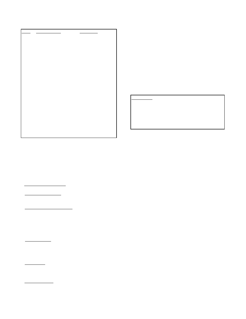
WARNING: Open valve and drain line before
removing cover bolts or pressure
may be released causing injury.
Place plug in lowest position before
removing actuator or plug may
rotate suddenly and jam or damage
plug surface.
ITEM DESCRIPTION
MATERIAL
1
Housing
Cast Iron
2
Plug
Plastic
3
Wormwheel
Ductile Iron
4
Shaft
Steel
5
Indicator
Cast Iron
6
Paint
Primer
7
Cover
Cast Iron
8
Worm
Hardened Steel
9
Bearing
Bronze
10
Bearing Race
Steel
11
Grease
EP-2
12
Worm Spacer
Steel
13
Gasket
Fiberflex
14
Pipe Plug
Steel
15
Expansion Plug
Steel
16
Jam Nut
Hardened Steel
17
Dowel Pin
Hardened Steel
18
Spirol Pin
Steel
19
1/4-20 Cap Screw
Steel
20
3/8-16 Cap Screw
Steel, Gr. 5
21
5/8-11 Set Screw
Steel
22
O-Ring
Buna-N
23
U-Cup Seal
Buna-N
TABLE 2. GEAR ACTUATOR PARTS LIST
TROUBLESHOOTING
Several problems and solutions are presented below
to assist you in troubleshooting the valve assembly
in an efficient manner.
• Leakage at Valve Shaft: Adjust or replace packing.
• Leakage at Flanges: Tighten flange bolts, replace
gasket.
• Valve Leaks when Closed: Pressure should be in
the direction of pushing the plug into the seat.
Adjust plug position by rotating the handwheel.
Inspect plug for damage and replace. Adjust
thrust bearing to lower plug if problem persists or
pressure direction is reverse.
• Hard to Open: Check thrust bearing adjustment;
raise plug. Check interior of valve for grit buildup
or debris. On buried valves, check alignment of
operating stem and nut.
• Leaking Oil: Tighten actuator cover bolts. If leak
persists, remove actuator cover, inspect grease,
and replace actuator gasket.
• Noisy Operation: Flow noise is normal. Loud flow
noise similar to hammering may be cavitation from
dropping high pressures across valve; review
application of valve. For gear actuator noise,
inspect grease; add new grease if there are
uncoated moving parts or grease has broken
down into oil.
DISASSEMBLY
Disassembly may be required to inspect the plug for
wear or remove debris and deposits from the valve.
Work on the valve should be performed by a skilled
mechanic with proper tools and a power hoist for
large valves. The valve can be disassembled without
removing the valve from the pipeline. Refer to Figure
2 for valve construction and parts.
1. Open valve and drain the pipeline. Rotate
handwheel until plug is between two seats.
Remove the indicator bracket and the small
cover on the actuator to expose the shaft key.
2. Remove the actuator mounting bolts and lift
actuator from valve taking care not to lose key
(24).
3. Remove cover bolts (15). Matchmark cover (2)
and body. Screw eye-bolts into actuator
mounting holes and use hoist to lift cover (2)
and plug assembly from valve. Use caution to
prevent plug from dropping while lifting cover.
To remove plug (3) from valve, use sling around
top portion of plug.
4. Inspection of the bearings (6) is done by
measuring diameter of shaft and inside diameter
of bearing. Check for a normal running
clearance of .005". The upper bearing can be
pressed out with bar smaller than the bearing
outside diameter. The lower bearing is removed
with a gear puller from inside the valve body.
Bearings are permanently impregnated with oil.
5. Thrust bearing assembly (23) and packing gland
(18) can be removed by removing all of the hex
nuts (12).