Val-Matic 30 and Larger Butterfly Valve User Manual
Page 6
5
VALVE T-BOLT RECOM. MAX.
SIZE DIA TORQUE TORQUE
(in) (in) (ft-lbs) (ft-lbs)
30
1
75
120
36
1
75
120
42
1-1/4
75
150
48
1-1/4
75
150
TABLE 2. MECHANICAL JOINT NUT TORQUES
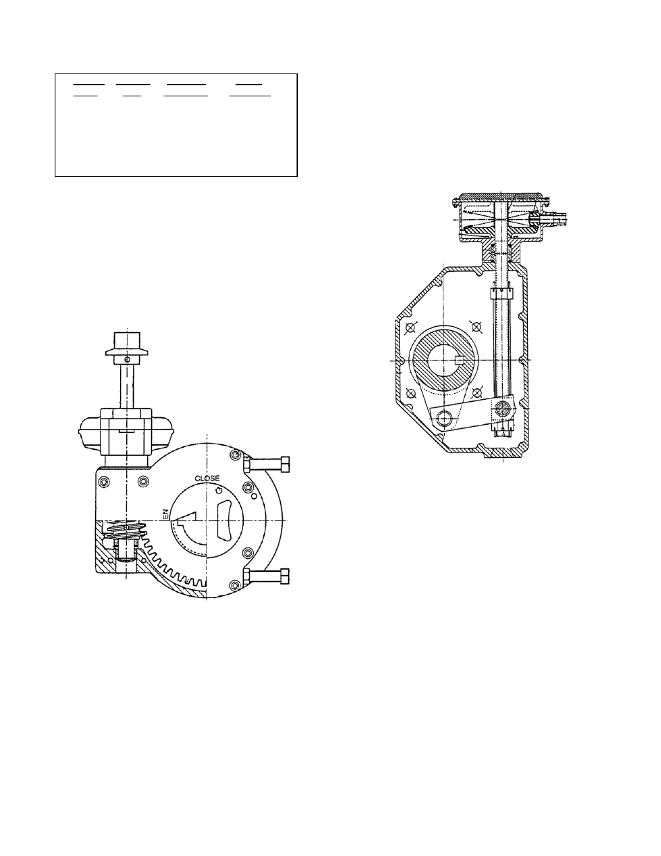
GEAR OPERATED VALVES: Butterfly Valves are
available with a two types of manual gear actuator.
A worm-gear actuator (Figure 6) has a multi-turn
worm that drives a large sector gear through 90
degrees of rotation. Worm gears provide uniform
motion and torque multiplication throughout the stroke.
A spur gear mounted on the input side provides
additional torque.
FIGURE 6. WORM GEAR ACTUATOR
A traveling nut actuator (Figure 7) has a threaded rod
that drives a nut from one end of the housing to
another. The traveling nut in turn drives a slotted lever
through 90 degrees of rotation. Traveling nut actuators
provide slower rotation and greater torque
multiplication at the ends of travel. A bevel gear
mounted on the input side of the actuator provides
additional torque.
FIGURE 7. TRAVELING NUT ACTUATOR
Both gear types are self-locking and multiply the
turning force on the handwheel or nut so that valves
can be operated with ease. A clamp-on chainwheel kit
can also be used for installations high above the floor.
An indicator on the top of the actuator housing
indicates the position of the valve plug. The
handwheel or nut must be rotated through 35-290 turns
(depending on model) to open or close the butterfly
valve. The direction of rotation to open the valve is
indicated on the 2" square actuator nut and handwheel.
The standard direction of rotation is open left or
counter-clockwise to open. Nuts with opposite rotation
(open right) will be painted red to indicate their special
rotation.
GEAR ACTUATOR ADJUSTMENT: The standard
gear actuator is provided with factory-set open and
closed position stops to properly center the closed disc
seal in the body seat. No field adjustment is
necessary.