Val-Matic 30 and Larger Butterfly Valve User Manual
Page 11
10
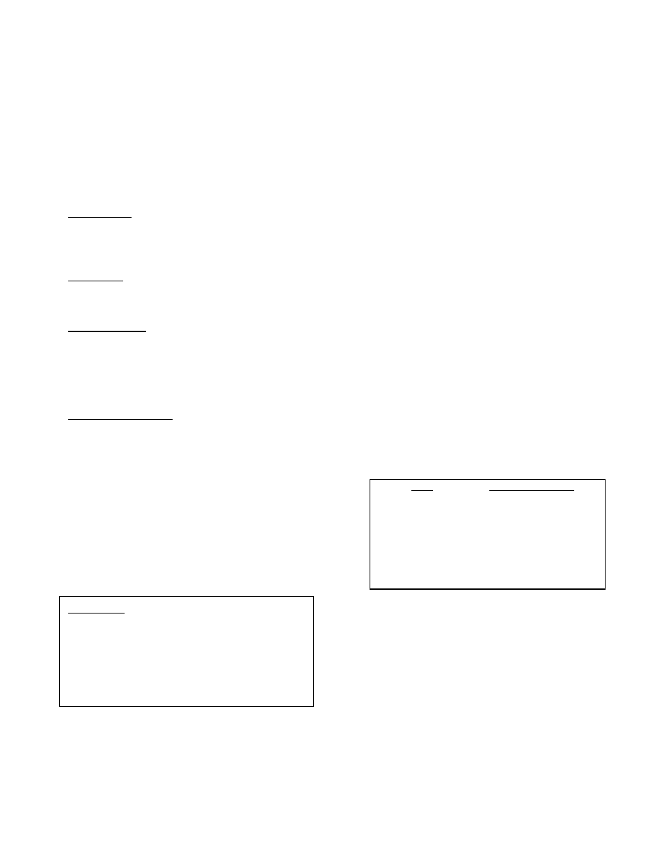
SIZE
TORQUE
(FT-LBS)
1/2"-13
45 - 75
5/8"-11
100 - 150
3/4"-10
150 - 250
7/8"-9
200 - 350
1"-8
300 - 500
1 1/8"-7
450 - 700
1 1/4"-7
650 - 1000
TROUBLESHOOTING (Cont’d)
4. Check the roundness of the adjoining pipe and pipe
flange. Pipe loads may cause distortion to the
adjoining pipe and valve.
5. Verify that the test pressure is less than the cold
working pressure (CWP) shown on the valve
nameplate.
Hard to Open: Flush line of debris. Check grease in
actuator. Check interior of valve for deposits or
debris. On buried valves, check alignment of
operating stem and nut.
Leaking Oil: Tighten actuator cover bolts. If leak
persists, remove actuator cover, inspect grease, and
replace actuator gasket.
Noisy Operation: Flow noise is normal. Loud flow
noise similar to hammering may be cavitation from
dropping high pressures across valve; review
application of valve. For gear actuator noise, inspect
grease; add new grease if there are uncoated
moving parts or grease has broken down into oil.
Valve does not Open: Remove actuator cover and
check internal parts. For mechanical joint valves,
heavy wall PVC pipes may interfere with the disc.
Chamfer pipe at 45 degrees.
DISASSEMBLY
Disassembly may be required to repair the valve.
Work on the valve should be performed by a skilled
mechanic with proper tools and a power hoist for large
valves. The valve must be removed from the pipeline
for disassembly. The actuator can be removed with
the valve in the line (the line must be drained) or after
the valve is removed from the line. Refer to Figure 14
for valve construction and parts.
1. Open valve slightly and drain the pipeline. Close
valve until disc edge just touches the seat. Valve
and actuator can be removed as a unit from the
pipeline.
2. Remove the small cover on the actuator to expose
the shaft key. Remove the actuator mounting
bolts and lift actuator from valve taking care not to
lose key (24). Access to the traveling nut actuator
will be under the actuator cover.
3. Remove lock cap (21) and thrust plate (18), and
thrust bearing cap (15). Remove the seat bolts
(8) and seat retaining ring (7).
4. Matchmark the taper pins with the disc holes.
Remove the taper pin nuts (11) and taper pins (9).
Press or hammer out the shaft (4) with a dead
blow hammer. The bearings (5) should not be
removed unless the teflon liner is severely worn.
To remove bearings, grind a slot along its length
and hammer out with a sharp chisel.
5. Clean and inspect parts. Replace worn parts as
necessary and lubricate parts with FDA grease.
REASSEMBLY
All parts must be cleaned and gasket surfaces should
be cleaned with a stiff wire brush in the direction of the
serrations or machine marks. Worn parts, gaskets and
seals should be replaced during reassembly. The
valve bolts should be lubricated and tightened per
Table 7 during reassembly.
TABLE 7. LUBRICATED BOLT TORQUES
1. Apply a bead of loctite 680 on new bearings (5)
and insert into both ends of the valve body (1) until
flush with packing bottom surface. Insert the
shafts (4) through the body and disc (3).
2. Install taper pins (9) with washers (12) and nuts
(11).
WARNING: Open valve and drain line before
removing actuator or the valve
may suddenly open causing
injury or fluid loss. Place valve in
closed or slightly open position to
remove from the line or damage
to the disc edge may occur.