Val-Matic Wastewater Combination Air Valve User Manual
Page 6
6
REASSEMBLY
All parts must be cleaned and gasket surfaces
should be cleaned with a stiff wire brush in the
direction of the serrations or machine marks. Worn
parts, gaskets and seals should be replaced during
reassembly. Refer to Figure 4.
1. Apply Loctite 680 thread sealant to guide bushing
threads (9) and thread bushing into baffle (3).
2. Lay seat (4), plug (16), and baffle (3) over
inverted cover and fasten with screws (28) with
maximum torque of 10 ft-lbs. Do not over tighten.
3. Assemble float (5) with Loctite 680 on the
threaded connections of float retainer (17) and
guide shaft retainer (35).
4. Insert pivot pins (12) through float arm (10) and
fasten with retainer rings (13). Thread in orifice
button (11) and secure with lockwasher (34) and
lock nut (18). Adjust orifice button so that when
float is seated against the plug, the button is
centered.
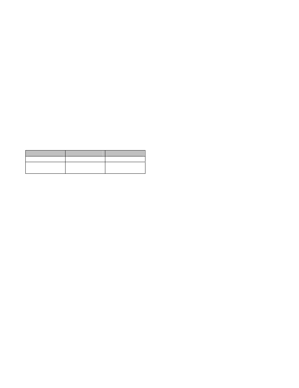
5. Lay cover gasket (6) over body flange and secure
with lubricated bolts (7) to the torque shown in
Table 2.
6. Place valve back in service. Refer to the
installation instructions on page 2. Slowly open
inlet isolation valve.
Model Number
Bolt Size
Torque (ft-lbs)
801A, 7/16” 30
802A, 803A,
804
1/2” 45
TABLE 2. VALVE COVER BOLT TORQUES
PARTS AND SERVICE
Parts and service are available from your local
representative or the factory. Make note of the valve
Model No and Working Pressure located on the
valve nameplate and contact:
Val-Matic Valve and Mfg. Corp.
905 Riverside Drive
Elmhurst, IL 60126
PH: 630/941-7600
FAX: 630/941-8042
A sales representative will quote prices for parts or
arrange for service as needed.
03/2007