Val-Matic Wastewater Combination Air Valve User Manual
Page 2
VAL-MATIC'S WASTEWATER COMBINATION AIR VALVE
OPERATION, MAINTENANCE AND INSTALLATION
INTRODUCTION
This manual will provide you with the information to
properly install and maintain the valve to ensure a
long service life. The Wastewater Combination Air
Valve has been designed with stainless steel trim to
give years of trouble-free operation but regular
maintenance is recommended for valves subject to
fluids containing suspended solids or greases/oils.
The Wastewater Combination Air Valve is typically
mounted at the high points in a piping system to
automatically remove pockets of air as they
accumulate. The valve can also be used to slowly
release air in tanks and pump casings.
2
CAUTION:
This valve is not intended for
flammable liquids service.
The valve is a float-operated, resilient-seated valve
designed to handle waste fluids. The valve may be
equipped with backwash accessories. The Size,
Maximum Working Pressure and Model No. are
stamped on the nameplate for reference.
RECEIVING AND STORAGE
Inspect valves upon receipt for damage in shipment.
Handle all valves carefully without dropping. Valves
should remain boxed, clean and dry until installed to
prevent weather related damage. For long-term
storage greater than six months, the valve must
remain in the box and stored indoors. Do not
expose valve to sunlight or ozone for any extended
period.
DESCRIPTION OF OPERATION
The Wastewater Combination Air Valve is designed
to automatically remove air pockets at the high
points in a piping system. The valve, as shipped, is
a normally open valve and will rapidly vent air
through the top opening. As fluid enters the valve,
the float will rise, closing the orifice. As air
accumulates in the piping system and enters the
valve, the float drops allowing the small venting
orifice to open.
The valve can be furnished with optional external
valves and hose connections for backwashing.
These items are packaged separately.
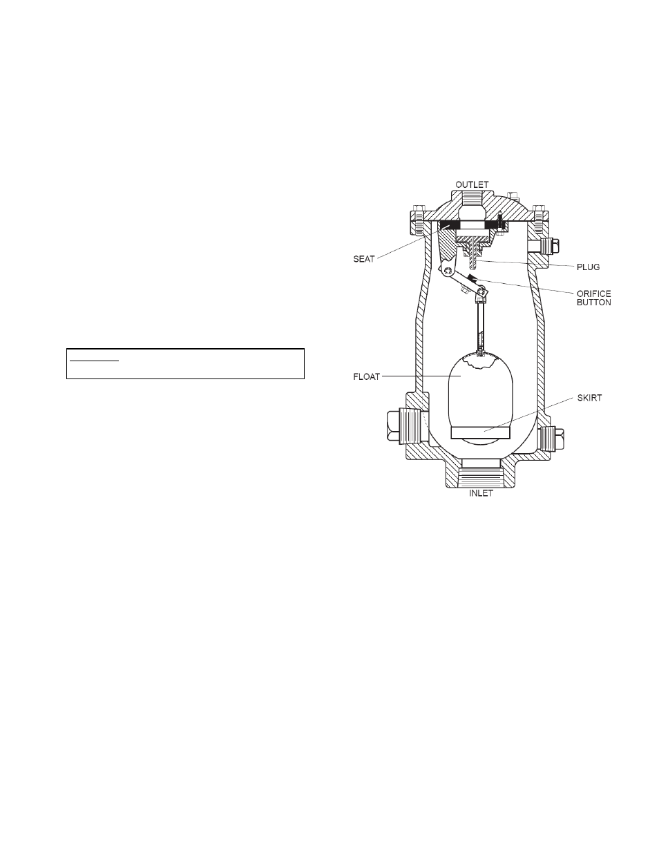
FIGURE 1. WASTEWATER COMBINATION AIR
VALVE
When air enters the valve, it is released through the
large-diameter seat and the outlet on the top of the
valve. When fluid enters the valve, the float lifts the
plug, which seals off the seat. The orifice button
also seals against the small orifice drilled through
the center of the plug. The float has a skirt to assist
in closure and reduce leakage. As air or gas
accumulates in the valve, the float will drop and pull
the button away from the plug. This will allow
pressurized air to be vented through the plug.
Additional ports are provided for flushing, testing and
draining purposes.