Val-Matic 4-20 Air/Vacuum Valve With Optional Anti-Slam Valve User Manual
Page 5
4
4. Lift float (5) from body. Turn guide
bushing (9) to remove it from body (1).
5. Clean and inspect parts. Note: some
floats contain sand for extra weight; if
water is detected, replace float.
Replace worn parts as necessary and
lubricate parts with FDA grease.
Remove all foreign matter from body
and cover.
REASSEMBLY
All parts must be cleaned and gasket surfaces
should be cleaned with a stiff wire brush in the
direction of the serrations or machine marks.
Worn parts, gaskets and seals should be
replaced during reassembly.
1. Apply thread sealant Loctite 680 to
guide bushing threads (9) and thread
bushing into body (1).
2. Lay seat (4) over inverted cover with flat
surface directed toward cover. Fasten
to cover with screws (8). Tighten
fasteners per Table 3.
3. Install float (5) through bushing (9).
4. Apply a gasket compound such as
Garlock 101-S to both sides of gasket.
Lay cover gasket (6) and cover (2) over
bolt holes in body (1).
5. Insert lubricated bolts (7) and tighten to
the torques listed in Table 3.
Size Torque (ft-lbs)
1/4" 6
5/16” 11
3/8” 19
7/16” 30
1/2" 45
5/8” 93
3/4" 150
7/8” 202
Table 3. Valve Bolts Torques
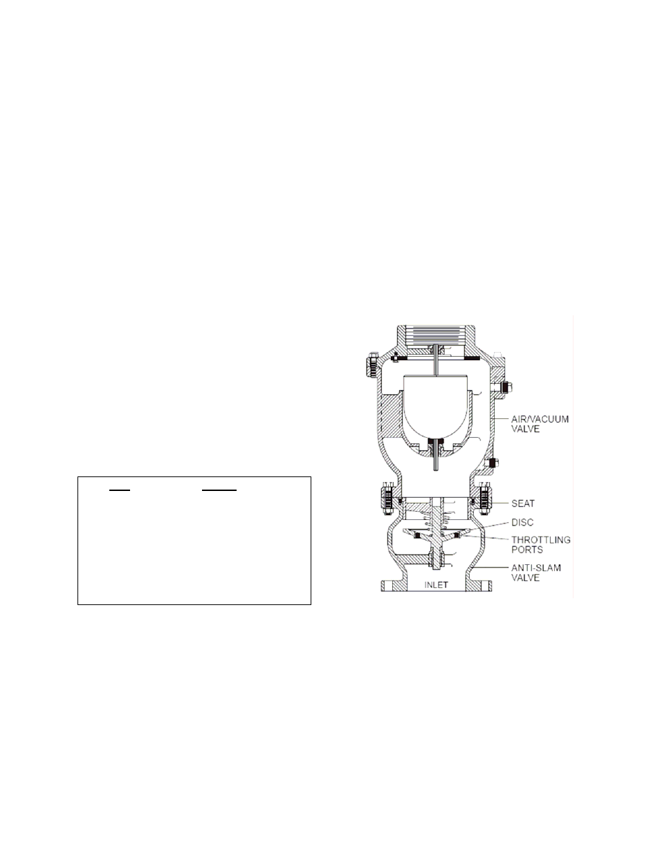
OPTIONAL ANTI-SLAM VALVE
DESCRIPTION OF OPERATION: Air/Vacuum
valves may be factory equipped with an anti-
slam valve on the inlet port as shown in Figure
4. The purpose of the valve is to prevent the
air/vacuum valve from being slammed shut
during critical operation such as after a sudden
pipeline flow stoppage.
The anti-slam valve is normally open and allows
unrestricted flow
of air in and out of the
air/vacuum valve. However, when water enters
the valve, it raises the disc to the closed
position. The passage of water is throttled
through small ports in the disc, which reduces
the possibility of shocks and water hammer.
Figure 4. Optional Anti-Slam Valve