Val-Matic 4-20 Air/Vacuum Valve With Optional Anti-Slam Valve User Manual
Page 3
2
INSTALLATION
The installation of the valve is important for its
proper operation. The valves must be installed
at the system high points in the vertical position
with the inlet down. For pipeline service, a vault
with freeze protection, adequate screened
venting, and drainage should be provided.
During closure, some fluid discharge will occur
so vent lines should extend to an open drain for
in-plant installations. A shutoff valve should be
installed below the valve in the event servicing is
required. A spool piece is required when mating
to a wafer butterfly valve.
FLANGED ENDS: Flanged valves should be
mated with flat-faced pipe flanges equipped with
resilient gaskets. When ring gaskets are used,
the bolt material shall be ASTM A307 Grade B
or SAE Grade 2 carbon steel.
Lower the valve over the mating flange using
slings or chains around the valve body.
Lubricate the flange bolts or studs and insert
them around the flange. Lightly turn bolts until
gaps are eliminated. The tightening of the bolts
should be done in graduated steps using the
crossover tightening method. Recommended
lubricated torque values, for use with resilient
gaskets (75 durometer), are given in Table 1.
If leakage occurs, allow gaskets to absorb fluid
and check the bolt torque and leakage after 24
hours. Do not exceed bolt rating or crush gasket
more than 50% of its thickness.
Valve
Size
(in)
Bolt
Dia
(in)
Recom.
Torque
(ft-lbs)
Max.
Torque
(ft-lbs)
4 5/8 30 90
6 3/4 30 150
8 3/4 40 150
10 7/8 45 205
12 7/8 45 205
14 1 80 300
16 1 90 300
18 1
1/8 100 425
20 1
1/8 120 425
Table 1. Flange Bolt Torques
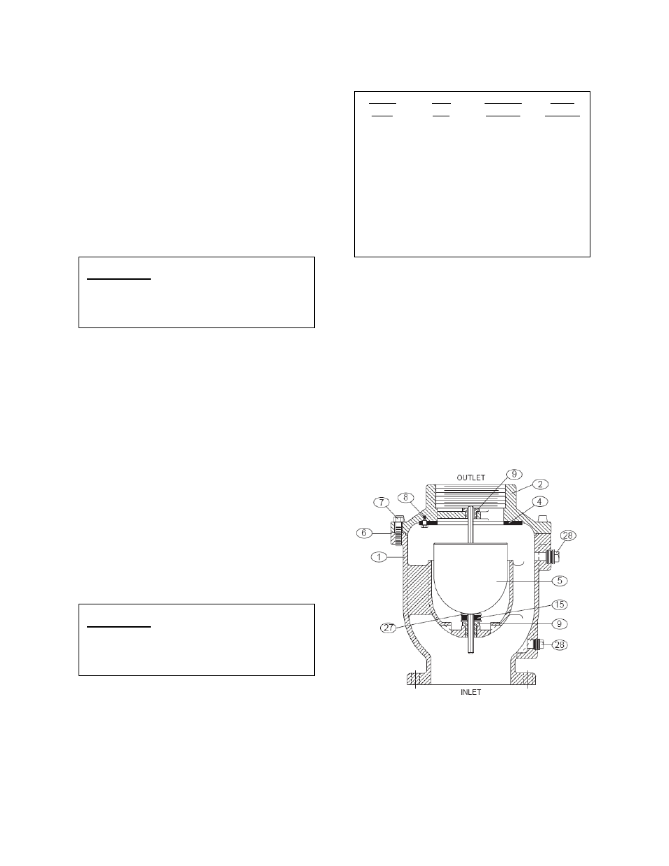
VALVE CONSTRUCTION
The standard Air/Vacuum Valve body and cover
are cast iron. See specific Materials List
submitted for the order if other than standard
cast iron construction. The internal metal
components are stainless steel. The float (5) is
the only moving part assuring long life with
minimal maintenance. The general details of
construction are illustrated in Figure 2. The
body (1) is flanged for connection to the pipeline.
The resilient seat (4) is retained in the cast cover
(2). An optional hood is available.
Figure 2. 4”-20” Air/Vacuum Valve
CAUTION:
Remove packing from
outlet and install valve
with “INLET” port down or
leakage will occur.
CAUTION:
The use of raised-face
flanges or excessive bolt
torque may damage valve
flanges.