Assembly, Warning, Warning danger warning – Powermate P-WLE-1639 User Manual
Page 7
Questions? Call Toll Free at 1-800-737-2112
Copyright © 2008 MAT Engine Technologies, LLC
Read and follow the assembly instructions. Do not discard any parts or materials until the unit is assembled.
References to the right or left side of the edger are from the viewpoint of the operator’s position behind the edger.
Do not operate edger if it is damaged or not completely and correctly assembled.
Before doing any assembly or maintenance to the unit, remove the wire from the spark plug.
Always wear ANSI compliant safety glasses with side shields while assembling the edger.
Assembly
• Save all instructions
1. Assemble the upper handle to the lower handle with the
(2) pipe bolts and the (2) plastic wing nuts. Firmly hand-
tighten the wing nuts.
2. Slide one end of the control rod into the hole of the
Depth Control Lever. Secure with hairpin.
3. Slide the other end of the control rod through the hole of
the quill arm. Secure with second hairpin.
4. Attach the recoil starter handle through the rope guide,
by twisting it into position.
5. Remove the temporary insert from the engine flameout
wire terminal.
6. Connect the flameout wires from the engine and handle.
Use cable tie to secure loose wire to handle.
The following components will be found in the carton.
Quantities shown in ( ).
1. (1) Edger
2. (1) Edger Operator’s Manual
3. (1) Upper Handle
4. (1) Control Rod
5. (1) Bottle of SAE 30 Engine Oil
6. (1) Parts bag containing the following:
(2) Hair Pins
(2) Plastic Wing Nuts (M8)
(2) M8x35mm Pipe Bolts
(1) Wire Tie
(1) Spark plug socket wrench w/ rod
1. Remove all parts and packaging components.
2. Use a utility knife to cut all 4 vertical edges and lay the
side panels flat around the edger.
3. Remove any remaining packaging.
4. Roll the unit out from the carton, and place on a hard
level surface.
How to Remove Edger from Carton
A
How to Assemble the Handle
B
Flameout wires MUST be connected for correct engine
operation. Failure to connect can result in serious injury.
If you need assistance or find any parts missing, CALL
TOLL FREE: 1-800-737-2112.
NOTE:
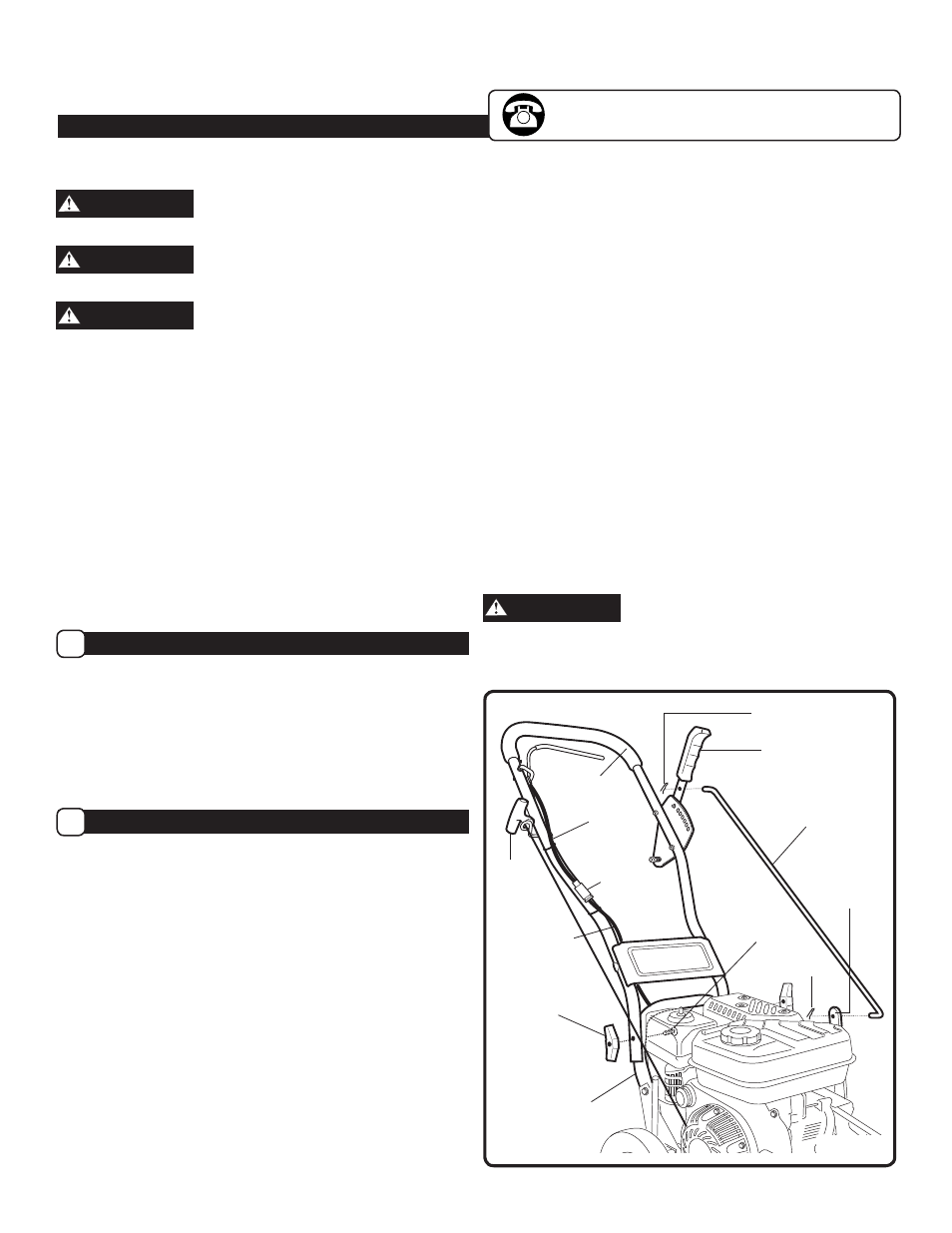
Refer to Figure 2 when following steps below:
6
WARNING
WARNING
WARNING
DANGER
WARNING
Upper
Handle
Lower
Handle
Hair Pin
Control Rod
Quill Support
Arm
Hair Pin
Pipe
Bolt
Figure 2
Depth Control
Lever
Recoil
Starter
Handle
Plastic
Wing Nut
Handle
Flameout
Wire
Engine
Flameout
Wire
Connection
Terminal