Asus M2N4-SLI User Manual
Page 44
2-24
Chapter 2: Hardware information
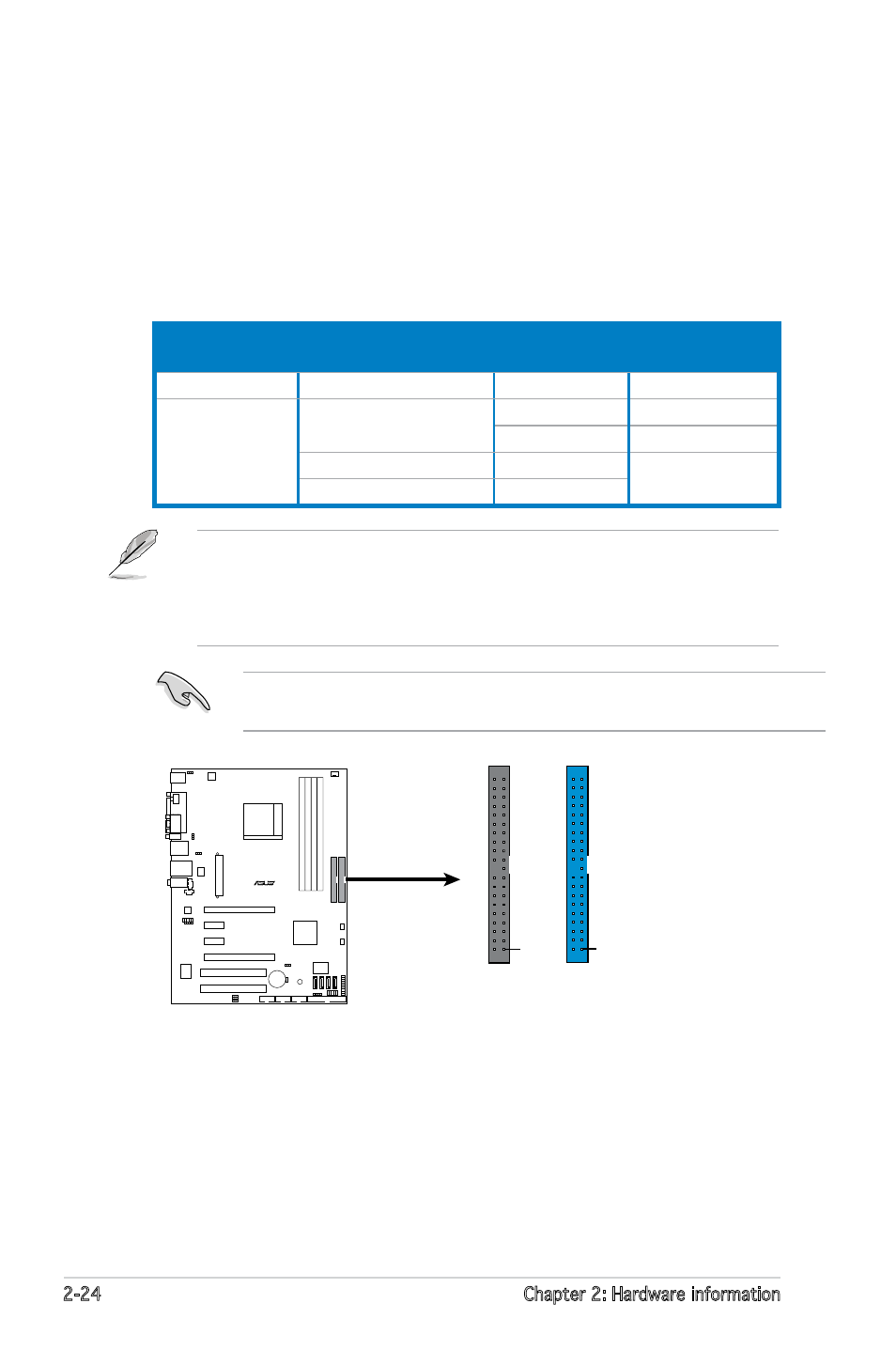
2. IDE connector (40-1 pin PRI_IDE, SEC_IDE)
The onboard IDE connector is for the Ultra DMA 133/100/66 signal
cable. There are three connectors on each Ultra DMA 133/100/66
signal cable: blue, black, and gray. Connect the blue connector to the
motherboard’s IDE connector, then select one of the following modes
to configure your device.
• Pin 20 on the IDE connector is removed to match the covered hole
on the Ultra DMA cable connector. This prevents incorrect insertion
when you connect the IDE cable.
• Use the 80-conductor IDE cable for Ultra DMA 100/66 IDE devices.
Drive jumper setting
Mode of
device(s)
Cable connector
Single device
Cable-Select or Master
-
Black
Two devices
Cable-Select
Master
Black
Slave
Gray
Master
Master
Black or gray
Slave
Slave
R
M2N4-SLI
M2N4-SLI
IDE Connectors
PRI_ID
E
SEC_ID
E
NOTE: Orient the red markings
(usually zigzag) on the ID
ribbon cable to PIN 1.
PIN
1
PIN
1
If any device jumper is set as “Cable-Select,” make sure all other device
jumpers have the same setting.
- Xonar DX (80 pages)
- Xonar DX (10 pages)
- PCI Express Audio Card Xonar DX (70 pages)
- Audio Card Xonar D2X (70 pages)
- Xonar D2X (88 pages)
- Xonar D2X (84 pages)
- D2X (88 pages)
- ROG Xonar Phoebus (72 pages)
- ROG Xonar Phoebus (122 pages)
- Xonar DSX (26 pages)
- Xonar DSX (29 pages)
- Xonar DGX (58 pages)
- Xonar DGX (38 pages)
- Xonar DGX (33 pages)
- Xonar DG (54 pages)
- Xonar DG (58 pages)
- Xonar DG (32 pages)
- Xonar DG (28 pages)
- Xonar Essence ST (35 pages)
- Xonar Essence ST (40 pages)
- Xonar Essence ST (53 pages)
- Xonar Essence ST (52 pages)
- Xonar DS (54 pages)
- Xonar DS (33 pages)
- Xonar Xense (47 pages)
- Xonar Xense (70 pages)
- Xonar Xense (45 pages)
- Xonar U3 (56 pages)
- Xonar U3 (38 pages)
- Xonar Essence STX (49 pages)
- Xonar Essence STX (10 pages)
- Xonar Essence STX (32 pages)
- XONAR D1 E4009 (72 pages)
- Xonar D1 (72 pages)
- Xonar D1 (80 pages)
- Xonar D1 (10 pages)
- Xonar Essence One (7 pages)
- Xonar Essence One (5 pages)
- Xonar HDAV 1.3 (100 pages)
- Motherboard M4A78-EM (64 pages)
- A7N8X-VM/400 (64 pages)
- K8V-XE (86 pages)
- K8V-XE (20 pages)
- M2R32-MVP (160 pages)
- M2R32-MVP (60 pages)