Operation – Lincoln Electric IMT10049 WIRE FEEDER WELDER 125, 140 User Manual
Page 12
B-3
OPERATION
B-3
WIRE FEEDER WELDERS (125, 140 MODELS)
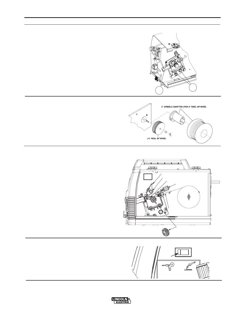
See Figure B.3
8. WELDING GUN CONNECTOR BUSHING &
THUMBSCREW – Provides electrical power to the
welding gun. The thumbscrew holds the welding
gun into the connector block. (Front Cover and Side
Door have been removed for clarity of Items 8 and
9).
9. OUTPUT TERMINALS - Connections to these ter-
minals determines the welding polarity, depending
on whether the process being used is flux-cored
welding or MIG welding.
See Figure B.4
10. WIRE SPOOL SPINDLE AND BRAKE – Holds a
4”(102mm) diameter spool. Use the 2”(51mm)
spindle adapter included with the machine for 8”
(203mm) diameter spools. The wing nut sets the
brake friction to prevent the spool from over rotat-
ing when the trigger is released. Tightening the
wing nut will prevent the spool from rotating when
the trigger is released.
See Figure B.5
11. WIRE DRIVE & COMPONENTS – Feeds wire
from the wire spool through the drive and through
the welding gun to the work piece.
a. Drive Roll – Drives the wire through the drive
system. The drive roll has grooves to match the
specific wire type and diameter. Refer to Table
B.1 for available drive rolls.
b. Incoming & Outgoing Guide – The wire is fed
through both guides. The Pivot Arm Assembly,
Tension Arm Assembly and Drive Roll keep
pressure on the wire in the groove.
c. Tension Arm Assembly – Turning clockwise
increases the forward force on the wire and turn-
ing counterclockwise decreases the force.
8
9
FIGURE B.3
FIGURE B.4
FIGURE B.5
FIGURE B.5a
WIRE SPOOL
.035" (0.9mm)
NR-211-MP
DRIVE ROLL
PIVOT ARM ASSEMBLY
TENSION ARM ASSEMBLY
OUTGOING GUIDE
INCOMING GUIDE
BEARING
See Figure B.5a
Magnum 100SG / Magnum 100L Switch - The spool
gun switch is available on 140 Amp machines only.
The Magnum 100SG Spool Gun can be purchased at
authorized retailers. The part number is K2532-1.
MAGNUM 100SG
SWITCH
MAGNUM 100L