Installation, A-5 external i/o connector, Status light – Lincoln Electric IM10021 MAXsa 19 CONTROLLER User Manual
Page 12: Selecting a wire drive and gear ratio
A-5
INSTALLATION
MAXsa™ 19 CONTROLLER
A-5
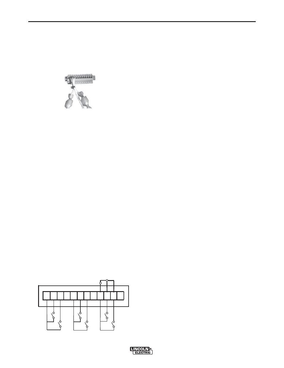
EXTERNAL I/O CONNECTOR
The MAXsa™ 19 is equipped with a terminal strip for
making simple input signal connections.(See Figure
A.3)
The terminal strip is divided into three groups:
Group #1 - START / STOP
Group # 2 - FEED FORWARD/REVERSE
Group #3 - SHUTDOWN INPUTS
When the Power Wave AC/DC 1000 SD is controlled
via DeviceNet, the “Start/Stop” and “Feed” groups can
interfere with the welding sequence and should not be
used.
All inputs use "normally open" logic except the shut-
down group. The shutdown inputs use "normally
closed" logic, and are always enabled. Unused shut-
downs must be tied to the +15V supply for the shut-
down group. Machines are shipped from the factory
with jumpers installed on both shutdown inputs. See
Figure A.4 for input Identification.
NOTES
1. Activating the “Start/Stop” or “Feed” group inputs
on a system without a user interface or other
means of configuring the Weld Sequencer will
result in default values for Weld Mode, WFS and
Work point settings.
2. “Start/Stop” and “Feed” group inputs may be rede-
fined as "Weld Profile Selections" by Production
Monitoring software (see Production Monitoring
Literature for details).
STATUS LIGHT
The Status Light is a two color LED that indicates the
system condition. Normal operation is steady green.
Flashing green or red/green indicates a system error.
See the Troubleshooting Section.
SELECTING A WIRE DRIVE
AND GEAR RATIO
The MAXsa™ 19 can accommodate a number of wire
drives including the MAXsa™ 22 and MAXsa™ 29.
The feeder control system must be configured for both
the wire drive and the gear ratio. This can be accom-
plished with the Weld Manager Utility. This utility is on
the Power Wave Submerged Arc Utilities CD, or avail-
able at www.powerwavesoftware.com.
FIGURE A.3 - EXTERNAL I/O
1
2
3
4
5
6
7
8
9
10
11
12
FIGURE A.4
E
1
2
3
4
5
6
7
8
9
10 11 12
A
B
+15VDC - Gr
oup #1
ST
AR
T
ST
OP
+15VDC - Gr
oup #2
Feed F
or
w
ar
d
Feed Rev
erse
+15VDC - Gr
oup #3
Shut
do
wn 1 I
nput
Shut
do
wn 2 I
nput
C
D
F