Installation, Warning – Lincoln Electric IM10067 CENTURY AC120 User Manual
Page 10
A-3
INSTALLATION
CENTURY® AC 120
A-3
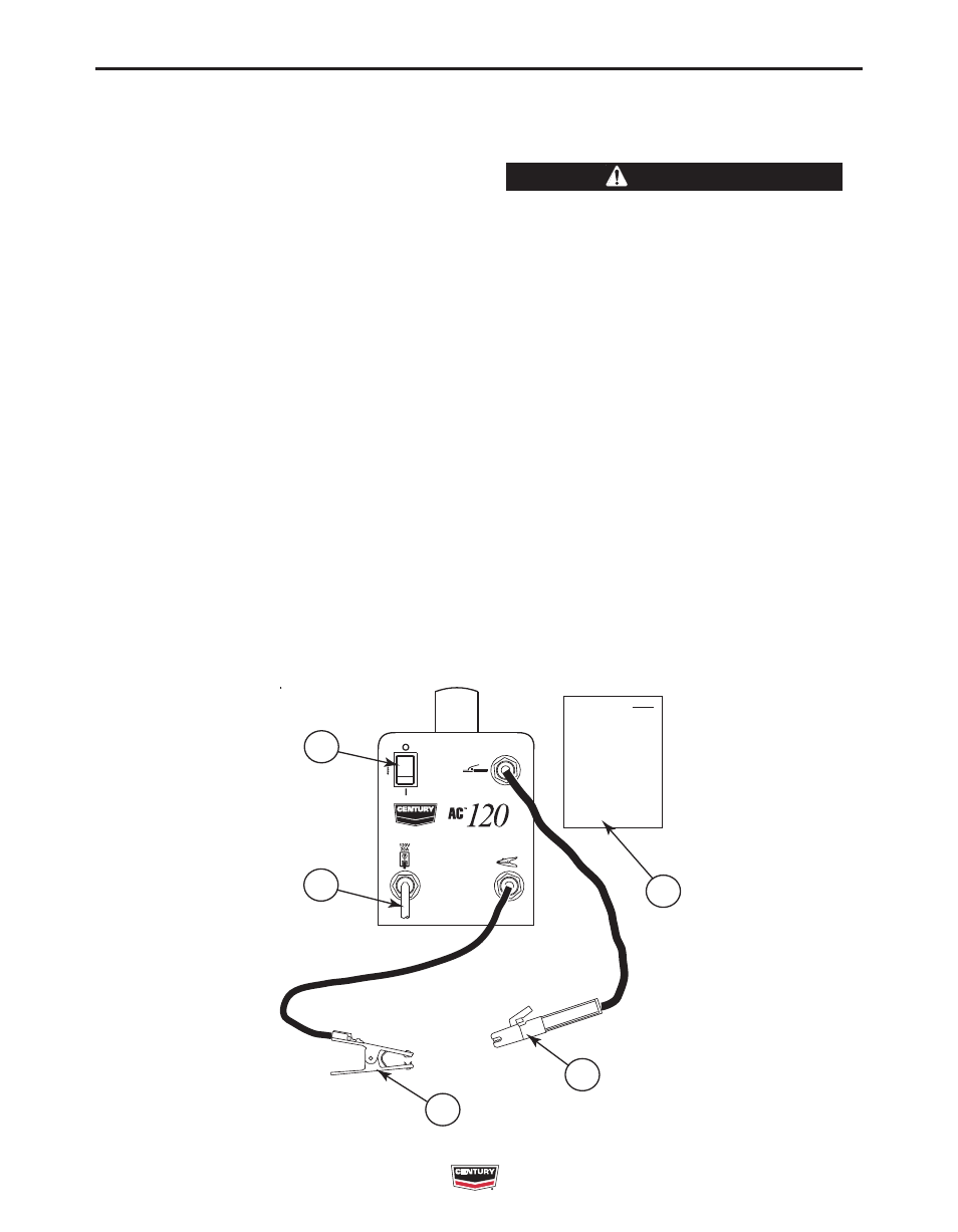
IDENTIFY AND LOCATE COMPONENTS
(See Figure A.1)
If you have not already done so, unpack the AC 120
from its carton and remove all packing material
around the unit.
1) INPUT CORD CONNECTION
This machine is intended to operate off a standard
household type receptacle (20A, 120V, 60Hz, sin-
gle phase, grounded). Refer to the Technical
Specifications at the beginning of this manual. If
connected to a circuit protected by fuses, use time
delay fuses marked "D".
2) WORK CLAMP
The work clamp and cable is attached to the
welder at the factory. The work clamp must be
directly connected to the workpiece or the work
bench. Make sure the contact to the workpiece is
adequate by avoiding painted or nonmetallic sur-
faces.
3) ELECTRODE HOLDER
The Electrode holder and cable is attached to the
welder at the factory. It has special contact jaws to
grasp the bare part of the welding electrode.
4) INSTRUCTION MANUAL
5) POWER SWITCH
INPUT CONNECTIONS
CODE REQUIREMENTS FOR INPUT
CONNECTIONS
• This welding machine must be connected to a
power supply in accordance with applicable elec-
trical codes.
• If there is any question about the installation
meeting applicable electrical code requirements,
consult a qualified electrician.
------------------------------------------------------------------------
Do not connect the AC 120 to an input power sup-
ply with a rated voltage that is greater than 125
volts.
Do not remove the power cord ground prong.
------------------------------------------------------------------------
WARNING
FIGURE A.1
1
2
3
5
4
CENTURY AC 120
1
2
3
5
4
CENTURY AC 120