Cartridge operation/features, Shade guide settings, Variable shade control knob – Lincoln Electric IM10147 AUTO-DARKENING HELMET User Manual
Page 8
CARTRIDGE OPERATION/FEATURES
Variable Shade Control
The shade can be adjusted from shade 9 to 13 based upon welding process or
application (refer to Shade selection chart on page 6). The variable shade control
knob is mounted on the exterior of the helmet shell. Grind mode can be selected
by rotating the shade control knob counterclockwise till an audible click is heard.
Grind mode is intended for grinding only not for welding.
Sensitivity Knob
You can adjust the light sensor by turning the Sensitivity knob to the left or right as
shown in figure below. Generally, turning the knob all the way to the right, or the
highest setting, is selected for normal use. When the helmet is used in the pres-
ence of excess ambient light or with another welding machine close by, improved
helmet performance can be obtained with a lower setting turning the knob to the left
to reduce the sensitivity.
Delay Time Knob
This control is designed to protect the welderʼs eyes from the strong residual rays
after welding. Changing the Delay Time knob will vary dark to light time between
.1 second (minimum) to 1.0 second (maximum). Turning the Delay Time knob to
the left is maximum (1.0 second). This setting is recommended for high amper-
age applications where the weld puddle is still very bright after the welding arc
has ceased and for situations where the filter may be temporarily blocked from
seeing the welding arc.
Power
This ADF cartridge is powered by replaceable batteries and solar power. Battery
installation is required prior to use. The batteries are located at the top of the
ADF cartridge. Replace batteries when LOW BATTERY light is lit. See the speci-
fication chart on page 3 for type of batteries required.
Variable shade
control Knob
5
ALWAYS TEST TO BE SURE THE ADF CARTRIDGE IS CHARGED
BEFORE WELDING. The TEST button is for the user to verify the ADF car-
tridgeis darkening properly. If cartridge is not darkening properly, replacebat-
teries with fresh batteries and test again before use. While welding, thearc
and solar cell will keep the ADF charged.
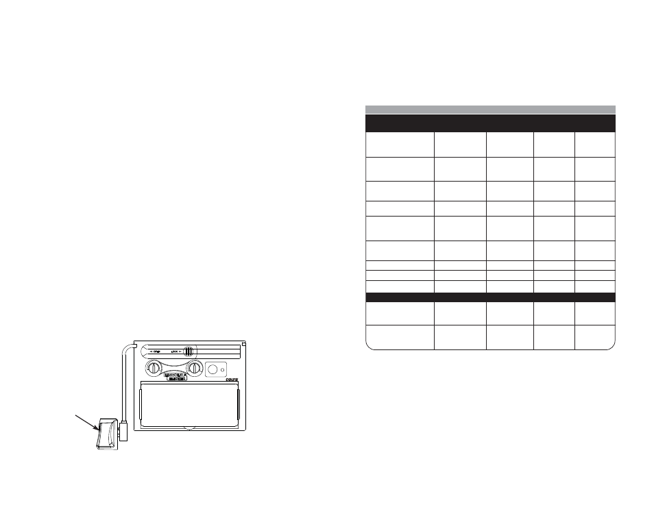
SHADE GUIDE SETTINGS
If your helmet does not include any one of the shades referenced above, it is
recommended you use the next darker shade.
6
L
H
T
I
S IV
N
E
S
ITY
L
S
L
E
D
AY
TEST
LOW
BATTERY
S27978-94
TMZ87W4/9-13
CAN/CSA Z94.3 /
GUIDE FOR SHADE NUMBERS
OPERATION
ELECTRODE SIZE
ARC
MINIMUM
SUGGESTED(1)
1/32 in. (mm)
CURRENT (A)
PROTECTIVE
SHADE NO.
SHADE
(COMFORT)
Shielded metal arc
Less than 3 (2.5)
Less than 60
7
–
welding
3-5 (2.5–4)
60-160
8
10
5-8 (4–6.4)
160-250
10
12
More than 8 (6.4)
250-550
11
14
Gas metal arc
Less than 60
7
–
welding and flux
60-160
10
11
cored arc welding
160-250
10
12
250-500
10
14
Gas tungsten arc
Less than 50
8
10
welding
50-150
8
12
150-500
10
14
Air carbon
(Light)
Less than 500
10
12
Arc cutting
(Heavy)
500-1000
11
14
Plasma arc welding
Less than 20
6
6 to 8
20-100
8
10
100-400
10
12
400-800
11
14
Plasma arc cutting
(Light)
(2)
(2)
(2)
Less than 300
8
9
(Medium)
300-400
9
12
(Heavy)
400-800
10
14
Torch brazing
–
–
3 or 4
Torch soldering
–
–
2
Carbon arc welding
–
–
14
PLATE THICKNESS
in.
mm
Gas welding
Light
Under 1/8
Under 3.2
4 or 5
Medium
1/8 to 1/2
3.2 to 12.7
5 or 6
Heavy
Over 1/2
Over 12.7
6 or 8
Oxygen cutting
Light
Under 1
Under 25
3 or 4
Medium
1 to 6
25 to 150
4 or 5
Heavy
Over 6
Over 150
5 or 6
(1)
As a rule of thumb, start with a shade that is too dark, then go to a lighter shade which gives sufficient view of the weld zone without going
below the minimum. In oxyfuel gas welding or cutting where the torch produces a high yellow light, it is desirable to use a filter lens that absorbs
the yellow or sodium line the visible light of the (spectrum) operation
(2)
These values apply where the actual arc is clearly seen. Experience has shown that lighter filters may be used when the arc is hidden by the
workpiece.
.
Data from ANSI Z49.1-2005