AT&T 585-350-812 User Manual
Page 45
3-5
ASAI Installation
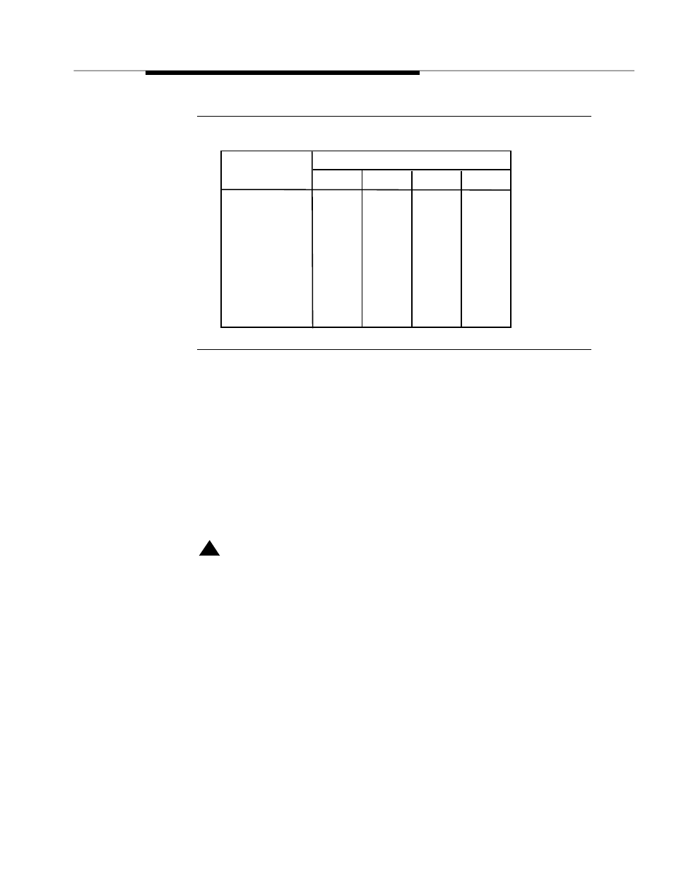
Figure 3-3.
IPCI Switch Settings
For information on installing the IPCI Card in the system, refer to Chapter 5,
“Installing Circuit Cards” in the hardware installation and upgrade book for your
platform.
Figure 3-4 shows a typical wiring architecture for the ASAI link.
Note that you must connect the AT&T 440A4 8-pin terminating resistor (or equiva-
lent) to the LINE connector of the IPCI Card using the provided DW8 cable. Use
the other DW8 cable to connect from the connecting block to the terminating
resistor.
!
CAUTION
:
Total cable length from the DEFINITY Generic 3i system to the VIS should
not exceed 1900 feet.
Base Address
Set These Switches
1
2
3
4
0c8000h
0cc000h
0d0000h
0d4000h
0d8000h
0dc000h
OFF
OFF
OFF
OFF
OFF
OFF
OFF
OFF
OFF
OFF
OFF
OFF
OFF
ON
ON
ON
ON
ON
ON
ON
ON
ON
ON
ON