C.1 dio i, Nterface, Ntroduction – IEI Integration NANO-9453 v1.10 User Manual
Page 230: C.2 dio c, Onnector, Inouts, C.1 dio interface introduction, C.2 dio connector pinouts
NANO-9453 EPIC Motherboard
Page 210
C.1 DIO Interface Introduction
The DIO connector on the NANO-9453 is interfaced to GIO ports on the iTE Super I/O
chipset. The DIO has both 4-bit digital inputs and 4-bit digital outputs. The digital inputs
and digital outputs are generally control signals that control the on/off circuit of external
devices or TTL devices. Data can be read or written to the selected address to enable the
DIO functions.
NOTE:
For further information, please refer to the datasheet for the iTE Super
I/O chipset.
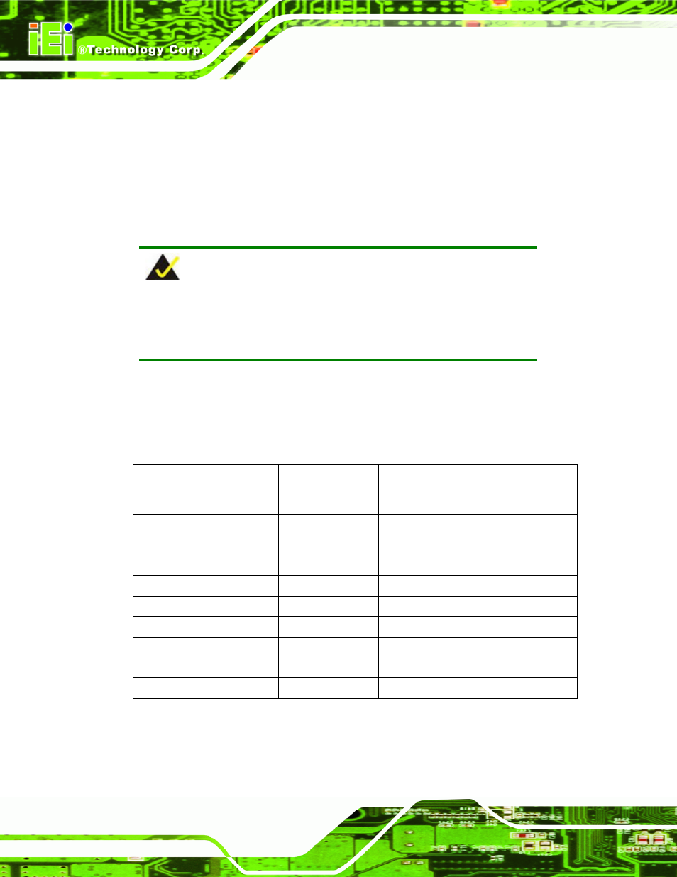
C.2 DIO Connector Pinouts
The following table describes how the DIO connector pins are connected to the Super I/O
GPIO port 1.
Pin No
Description
Super I/O Pin
Super I/O Pin Descripton
1 Ground N/A
N/A
2 VCC
N/A
N/A
3
Output 0
GP14
General purpose I/O port 1 bit 4.
4
Output 1
GP15
General purpose I/O port 1 bit 5.
5
Output 2
GP16
General purpose I/O port 1 bit 6.
6
Output 3
GP17
General purpose I/O port 1 bit 7.
7
Input 0
GP10
General purpose I/O port 1 bit 0.
8
Input 1
GP11
General purpose I/O port 1 bit 1
9
Input 2
GP12
General purpose I/O port 1 bit 2
10
Input 3
GP13
General purpose I/O port 1 bit 3