Connectors, Installation guide, Pin assignment – IEI Integration PX-10S-RS v1.01 User Manual
Page 5: Chassis, Power supply
4
PX-10S User’s Manual
Connectors
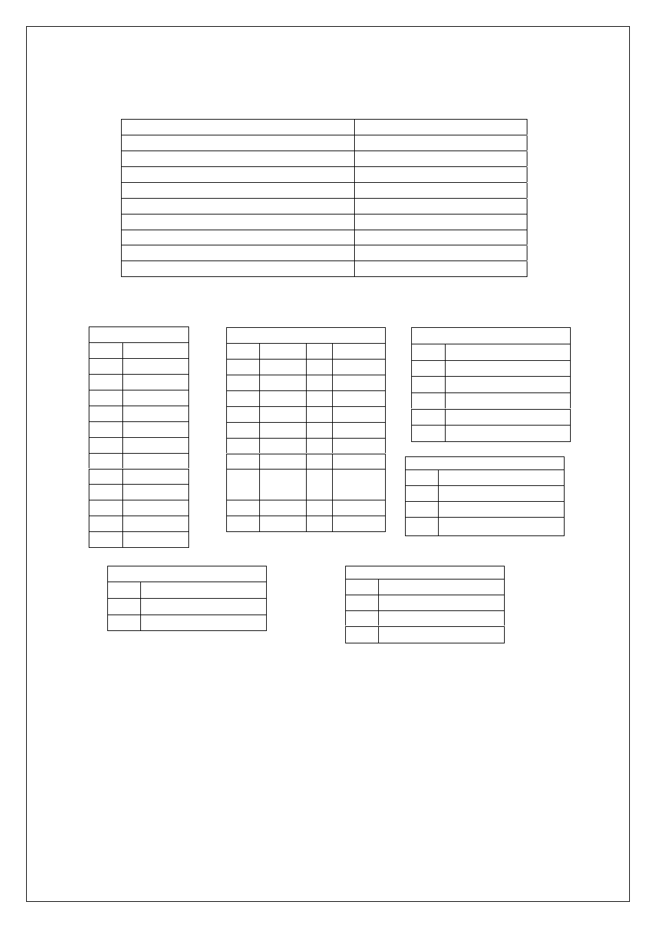
CONNECTOR DESCRIPTION
ISA2/PCI1 & ISA4/PCI2
PICMG connectors
PCI3-PCI9
32-BIT PCI BUS connectors
ISA1,ISA3
16-BIT ISA BUS connectors
PW1
P8/P9 power connector
PW2 ATX
power
connector
CN1
DC power outlet
CN2
ATX P/S control connector
CN3,CN5 Fan
connector
CN4
Power good signal output
Pin Assignment
Installation Guide
Chassis
Make sure the copper lifting stands are placed below all the mounting holes of your backplane.
SBC
Apply only one full-sized SBC over PICMG slot or half-sized SBC over ISA slot.
Apply your ISA/PCI cards over ISA/PCI slot (Image 1).
Power Supply
1.If you use AT power supply, attach the P8/P9 connector to PW1 (Image. 2).
2.If you use ATX power supply, attach the 20-pin ATX power connector to PW2 (Image. 3).
Besides, you need to apply one 3-pin ATX power control cable between your SBC and backplane
Power Extension(CN1)
PIN
NAME
1 +5V
2 -5V
3 -12V
4 +12V
5 GND
ATX(PW2)
PIN NAME PIN NAME
1 +3.3V
11
+3.3V
2 +3.3V 12
-12V
3 GND
13
GND
4 +5V 14 PS_ON
5 GND
15
GND
6 +5V 16
GND
7 GND
17
GND
8
PWR
OK
18
-5V
9 STB5V 19
+5V
10 +12V 20
+5V
P8/P9(PW1)
PIN NAME
1 PWR
OK
2 +5V
3 +12V
4 -12V
5 GND
6 GND
7 GND
8 GND
9 -5V
10 +5V
11 +5V
12 +5V
ATX control connector(CN2)
PIN NAME
1 STB5V
2 PS_ON
3 GND
Fan connector(CN3,CN5)
PIN
NAME
1 NC
2 +12V
3 GND
Power Good output(CN4)
PIN NAME
1 Power
Good
2 GND