Avi exhaust hood – XLT XD-9004B User Manual
Page 39
39
Technical Support US: 888-443-2751
Technical Support INTL: 316-943-2751
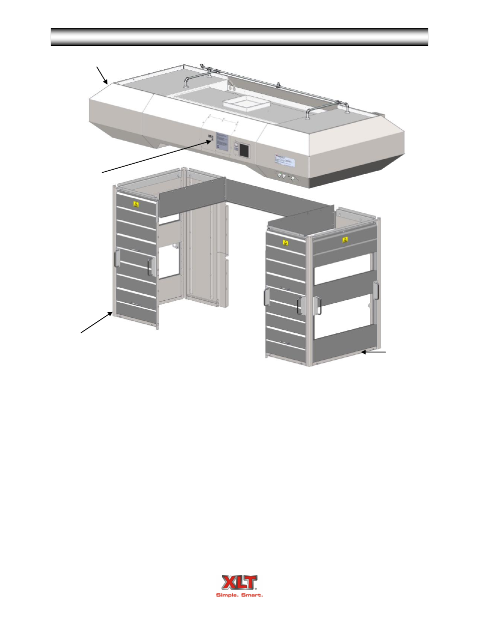
HOOD DESCRIPTION
AVI EXHAUST HOOD
End Shroud
Panel
Front
Shroud
Panel
Main Canopy
The AVI Hood System consists of three (3) major parts; the Main Canopy, the Shrouds,
and the Variable Frequency Drive (VFD) exhaust fan controller.
The Main Canopy serves to collect and transmit heat to the exhaust fan. It houses filters,
lights, and switches. The switches control both the hood and ovens. The main canopy size is de-
pendent upon oven size.
The Shrouds assist the efficiency of the main canopy by entrapping heat. They are config-
urable for either side or end loading or unloading, and are easily removable for cleaning and main-
tenance.
The VFD converts input power to variable frequency three-phase output power to control
the speed of the exhaust fan. All electric utilities for the hood and exhaust fan connect through the
electrical box located on the rear of main canopy. The operator switches are located on the control
panel on the front of main canopy, and interlock the function of the hood and oven(s). There are
optional relays that provide interlocks for equipment such as, fire suppression, HVAC dampers,
and/or dedicated MUA units.
All AVI hoods are available pre-piped for fire suppression, allowing for simple, in-field
installations.
VFD Exhaust
Fan Controller