Pnc2 installation instructions - fixing, 3 installation - fixing, Close panel/box – TREND PNC2 User Manual
Page 4: Configure/commission, Connect auxiliary supply output, Connect to printer
1 - 4
PNC2 Printer Node Controller Installation Instructions TG200264 Issue 1/D 22/07/04
PNC2
Installation Instructions - Fixing
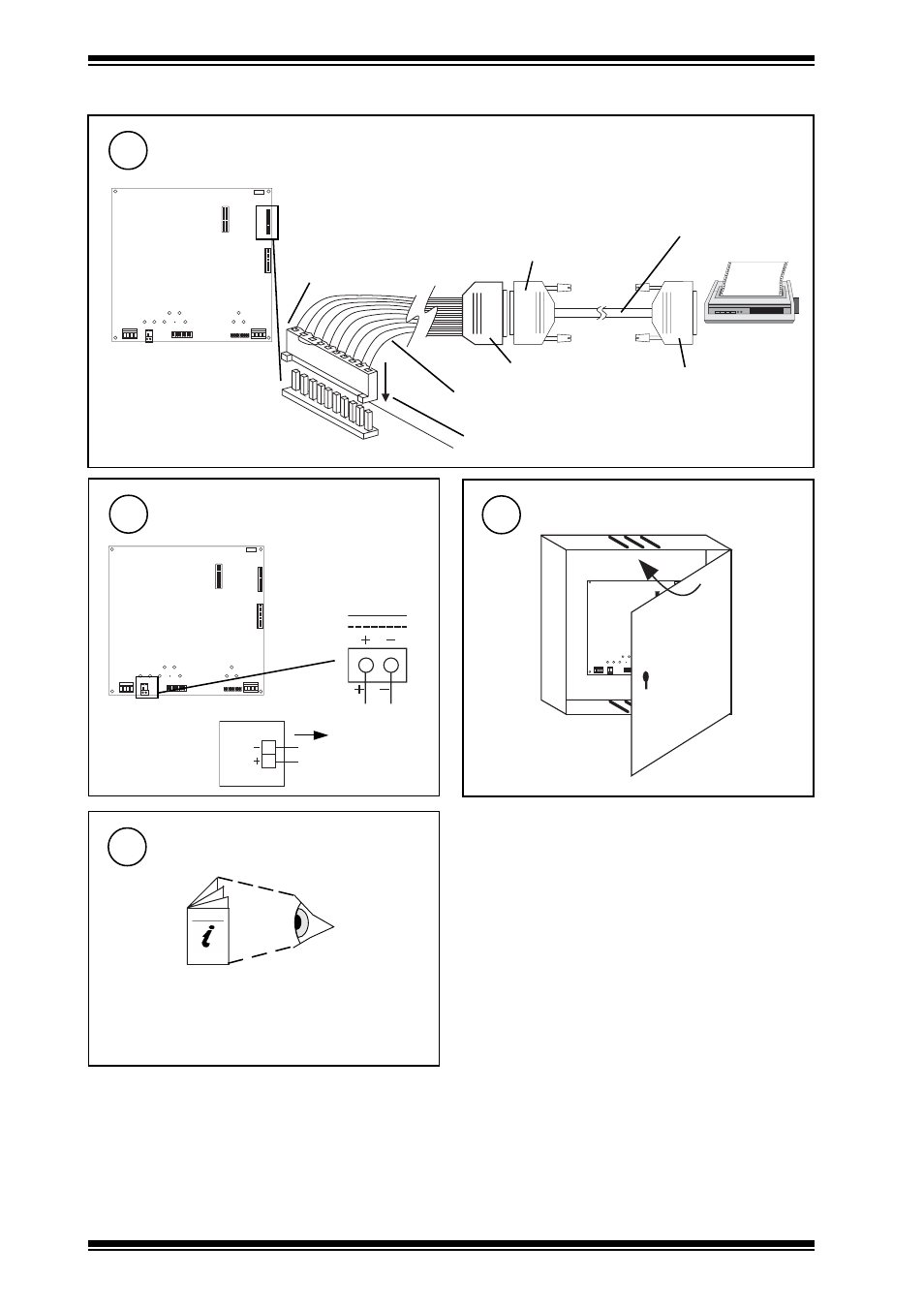
Close Panel/Box
10
J 7
E T 1
J 1 6
D e v B
J 1 5
D e v A
J 8
L a n A
J 1 7
Configure/Commission
11
PNC2 Installation Instructions - Sheet 2: Configuration
2
1.3 Installation - Fixing
(continued)
Connect Auxiliary Supply Output
9
J 7
E T 1
J 1 6
D e v B
J 1 5
D e v A
J 8
L a n A
J 1 7
24 V
PNC2
24 V
I max = 150
mA
AUX
1
J 7
E T 1
J 1 6
D e v B
J 1 5
D e v A
J 8
L a n A
J 1 7
Connect to Printer
8
cables not supplied with unit
Dev B
10 Way, Molex, Female
links between pins 2-4, 3-5
25 Way, D type, Female
CABLE/EJ100179A001
25 Way, D type, Male
25 Way D type male to male
cable, pins 3, 7, 20 connected
straight through
25 Way, D type, Male
J16
(Device B - RS232)
Ensure correct polarity
1
terminal size 0.5
to 2.5 mm
2