Features – Staub Electronics EA-AMP-SUB-1D-110 EPISODE - DIGITAL SUBWOOFER AMP 110 WATT W_ 12V TRIGGER User Manual
Page 3
© 2011 Episode
EA-AMP-SUB-1D-110 Installation and Users Manual
pg.3
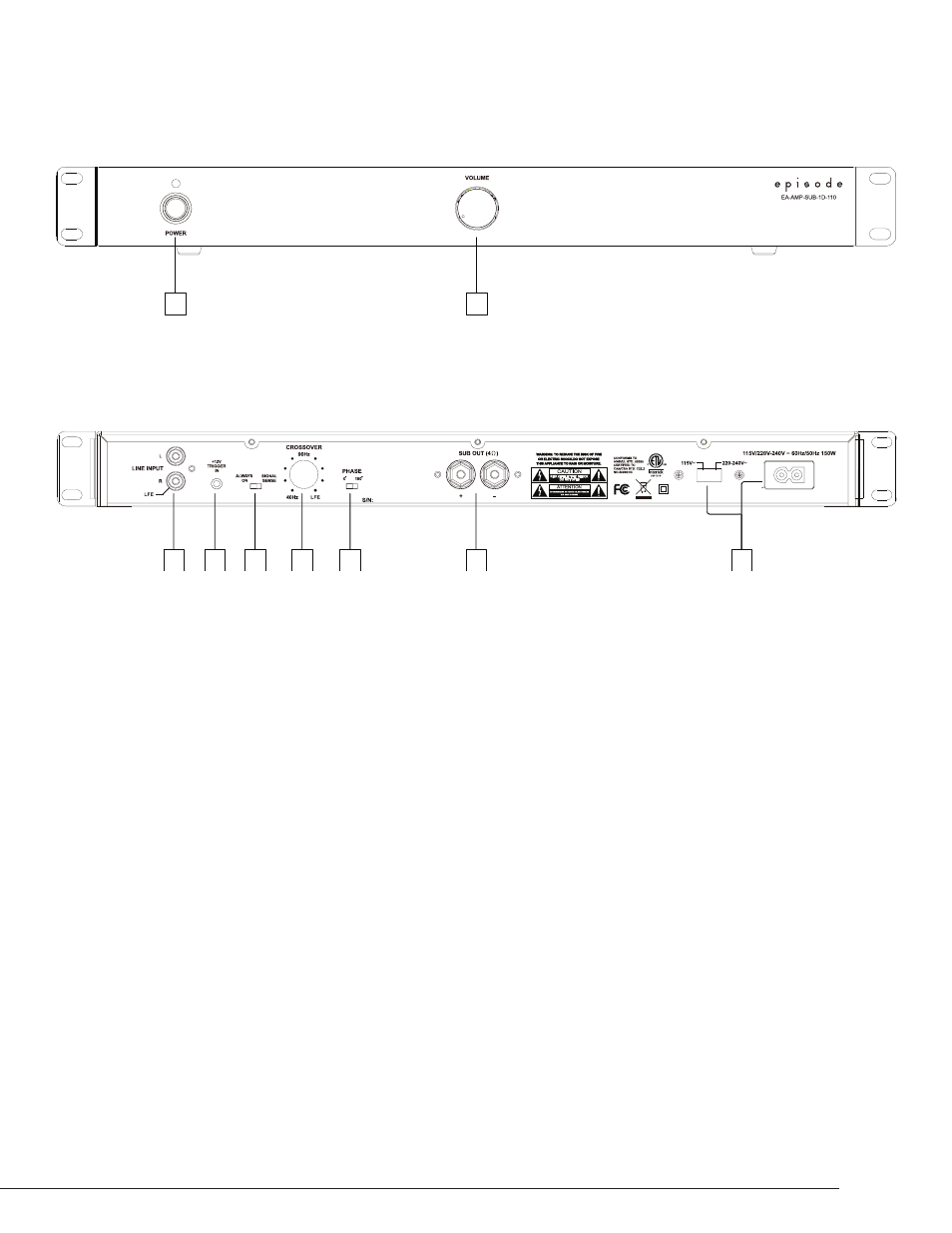
FEATURES
1. Power Switch
a. RED – Off/Standby
b. Blue – On/Operating
2. Output Volume Control
1
2
2
3
4
5
6
7
1
Engineered in the USA
Manufactured in China
1. AUDIO INPUTS
a. Connect the Right Female RCA input to an LFE output connection on a receiver or pre-amp processor.
b. Connect the Left and Right Female RCA input to the Left and Right front output. connections on a receiver or
pre-amp processor.
NOTE: Both inputs have been calibrated to the same sensitivity level. When using stereo pre-amp outputs, both connections should be
used to maintain proper input gain.
2. 12V Trigger In
a. Connect the 12V trigger output of the AV receiver to turn amp on when a 12V signal is received.
When using a 12V trigger, the Power Mode settings do not apply. See System Connections for more information.
3. POWER MODES
a. ON – Always On
b. Signal Sense – On, triggered via signal sense; when signal is off, amp will stay on for approximately 15 to 20 minutes.
4. CROSS-OVER
Crossover frequency setting of the Low Pass Filter can be adjusted from 40 to 140 Hz.
NOTE: When using the LFE input, set to LFE so the preamplifier or receiver can control the crossover frequency.
5. PHASE
The phase of the subwoofer can be adjusted to fine tune the alignment of subwoofer signals and with those
from the main speakers. Adjust the phase, listening for an increase in mid bass in the crossover region.
6. SPEAKER OUTPUTS
a. Connect the speaker wires to the Binding Posts. NOTE: Red is Positive and Black is Negative.
Bridged output, do not ground.
b. Use Bare Speaker Wire, Spade Lugs, or Banana Plugs to terminate the speaker wire.
7. AC POWER
a. Input voltage setting selects the appropriate 115V or 230V setting.
b. IEC Power Cord