Staub Electronics SM-PROJ-L-WH STRONG - UNIVERSAL PROJECTOR MOUNT FOR PROJECTORS UP TO 50LBS User Manual
Page 2
INSTALLATION INSTRUCTIONS
Step 1: Use Ceiling Plate to Mark Mounting Hole Locations (Low-Profile or Extension)
a. The use of a stud finder is highly recommended. When mounting the Low-Profile Ceiling Plate,
make sure arrow on bottom of the Low-Profile Ceiling Plate faces toward the screen.
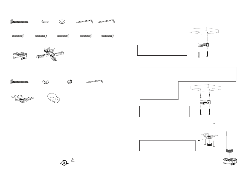
Step 2: Mount the Ceiling Plate
Low-Profile Ceiling Plate
For Mounting on a Wood Joist (Fig. 1)
a. Pre-drill two holes into joist using a 3/16” drill bit.
Be sure to drill into the center of the joists.
b. Insert two Lag Screws into holes through the
Low-Profile Ceiling Plate and tighten down.
WARNING: Tighten screws so that the Low-Profile
Ceiling Plate is firmly attached, but do not over-
tighten. Over-tightening can damage the screws,
greatly reducing their holding strength.
For Mounting on a Concrete Ceiling (Fig. 2)
a. Pre-drill two holes into concrete using 3/8” Masonry bit. Insert Concrete Anchors and
tap in with hammer, if necessary.
WARNING: When installing Ceiling Plate on cinder block, first verify there is a minimum of 1-3/8”
of concrete thickness to be used for the Concrete Wall Anchors. Do not drill into mortar joints!
Be sure to mount in a solid part of the block, generally 1”minimum from the side of the block.
Cinder block must meet ASTM C-90 specifications. It is suggested that a standard electric drill on slow
setting is used to drill the hole instead of a hammer drill to avoid breaking out the back of the
hole when entering a void or cavity.
Concrete must be 2000 psi density
minimum. Lighter density concrete
may not hold concrete anchor.
Make sure that the supporting surface
will safely support the combined load
of the equipment and all attached
hardware and components.
b. Insert two Lag Screws into the Concrete
Anchors through the Low Profile Ceiling Plate.
WARNING: Tighten screws so that the Low-Profile
Ceiling Plate is firmly attached, but do not over-
tighten. Over-tightening can damage the screws,
greatly reducing their holding strength.
Extension Ceiling Plate
For Mounting on a Wood Joist (Fig. 3)
a. Use Extension Ceiling Plate to mark two hole locations.
Pre-drill two holes into joist using a 3/16” drill bit. Be sure
to drill into the center of the joists.
b. Insert two Lag Screws into holes through the Extension
Ceiling Plate and tighten down.
WARNING: Tighten screws so that the Low-Profile Ceiling
Plate is firmly attached, but do not over-tighten. Over-
tightening can damage the screws, greatly reducing their
holding strength.
c. Thread Extension Pole (UL Listed SM-FIXPOLE series, not included)
into Extended Ceiling Plate. Lock pole in place with two M5 set screws.
d. On bottom of Extension Pole, thread on Low-Profile Ceiling
Plate, making sure the arrow (on bottom) faces the screen
when installed. Tighten Security Screw (pre-installed) to lock
Low-Profile Ceiling Plate onto Extension Pole to set in place.
#14 x 2.5”
Lag Screw (x4)
#14 x 2.5”
Lag Screw (x4)
Extension Ceiling Plate (x1)
Extension Plate Cover (x1)
M3x8 Socket
Screw, security (x4)
Low-Profile Ceiling
Plate (x1)
Projector Mount
Body (x1)
M4x10 Socket
Screw, security (x4)
M5x10 Socket
Screw, security (x4)
M6x10 Socket
Screw, security (x4)
10-32X10 Socket
Screw, security (x1)
10x50 Concrete
Anchor (x4)
4mm (ID) Washer
(x4)
4mm (ID) Washer
(x4)
M5x5 Set Screw,
security/non-security
(x2/2)
2mm Allen Wrench,
security (x1)
2mm Allen Wrench,
security (x1)
4mm Allen Wrench,
security (x1)
HARDWARE KIT
SPECIFICATIONS
• Maximum load: 50 lbs (22.68 kg).
• Tilt range: +/- 25º
• Roll: +/- 6º
TOOLS REQUIRED
• Philips Head Screw Driver
• Power Drill
• 3/16” (5 mm) Drill Bit
• 3/8” (10 mm) Masonry Bit
• Stud Finder
• 10mm or 3/8” Socket
Head Wrench
WARNINGS
• We highly recommend this product be installed
by a qualified professional.
• Do not begin installation until you have
thoroughly read and understand these instructions.
• This mount supports projectors with a maximum load
of 50 lbs (22.68 kg).
• Ensure the ceiling will safely support four times the
combined weight of the mount and projector.
• Under no circumstances should this product
be mounted to metal studs.
• The manufacturer does not accept responsibility
for incorrect installation.
MAIN PACKAGE CONTENTS
EXTENSION PLATE CONTENTS
Fig 1
Fig 2
Fig 3
CAUTION:
This mount is intended for use only with
the maximum weight of 50 lbs (22.68kg).