SR Products ETL121375 Nominal Temperature Rating User Manual
Page 3
Installation Instructions
The ETL® is typically mounted on dampers in ductwork; roof hatches; fire doors, and for other uses
where retrofit or replacement of standard fusible links of forty pound rating ( or less ) is desired. It is typically
attached mechanically by placing metal straps or “S” hooks through the square link halve openings to provide
a “floating” linear force tension of 7# minimum, 40# maximum continuous load. The ETL® has a forty (40)
pound maximum continuous tensile strength at standard temperature (which can only be achieved in
installations where the link is subject to equal linear tension). If side or “peel” forces are encountered (which is
typical in most smoke damper installations) the weight may have to be reduced, or the tension vectors re-
established. For this reason it is not permissible to bolt or fix one end of the ETL in most installations. Even if
the Installation is gravity release (i.e. forty (40) pounds hanging straight down from the bottom of the link) it is
recommended to allow the link to “float” using “S” hooks, straps or other attachments.
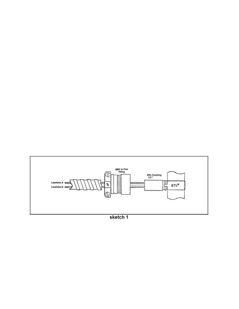
Accordingly, the ETL attachment end is the same diameter as ½” EMT tubing permitting standard UL
listed ⅜” or ½” flex to ½“ EMT connectors to be used together with the appropriate flexible conduit to
completely encase the wires within the duct as illustrated in sketch 1. Note that the conduit should run in a
substantially level, straight line with a minimum length and slack, to either side of the duct, assuring it cannot
be trapped under the damper blades upon closure. Always mount the junction box outside the duct on the top
or either side at a point at or above the level of the ETL when mounted on the damper.
The ETL® is typically wired by running the yellow lead wires (Leadwire A and Leadwire B sketch 1)
from the ETL® to a pair of Normally Open [NO] terminal contacts (Lead wire A to [NO] contact 1 and Lead Wire
B to [NO] contact 2). Polarity is irrelevant. Actuating supply current is typically provided by an NEC class 2 low
voltage 6-30 VAC/DC (or other) source capable of delivering 0.2 ampere (200 milliamperes) minimum for 50
milliseconds minimum duration to each unit wired in parallel to the [NO] contacts.
ETL375F
Rev. D
2/24/12
Page 3 of 4