Standard features, Optional features, Technical data – Southern Folger 10300M MOTOR OPERATED ELECTRO-MECHANICAL DEADLATCH User Manual
Page 2
P.O. BOX 2021 • SAN ANTONIO, TX • 78297 • 210-533-1231 • FAX: 210-533-2211
Revised
12/10
STANDARD FEATURES:
• Deadlock indication switch
• Mechanical latchback
• Strike with security fasteners
• Faceplate with security fasteners
• Plug connector
• High torque motor
• Fail secure
• Mounting fasteners
Note #1: 1-11/16” O.D. x 1/8” wall
cold drawn tubes furnished by
hollow metal manufacturer.
OPTIONAL FEATURES:
HALF CYCLE HOLDBACK -
Remote two-position maintained
contact switch is required for this
function. Latchbolt is retracted
electrically when switch is in open
position. When remote switch is
returned to locked position, latch
bolt will extend when door is
opened approximately 2".
Specify “D.” UL listing not
available with this function.
NO LATCHBACK - Allows latch
bolt to extend without opening
door. Normally used with “D”
function. Specify “NL.”
LOCAL ELECTRIC KEYSWITCH -
Day key provides local electric
operation and may be disabled
from remote control point. Master
key provides both electric and
mechanical operation. Requires
dual-function enhancement to
builder's cylinder. Specify “LEK.”
BUILDER’S HARDWARE
CYLINDERS -
Specify:
• “10300M-1” keyed one side.
• “10300M-2” keyed both sides.
KEY CYLINDER EXTENDER -
Required whenever lock is keyed
on stop side. Overall frame depth
4" minimum. Specify “KCE.”
Full body rim cylinder required on stop side.
Full body mortise cylinder required on
hinge side.
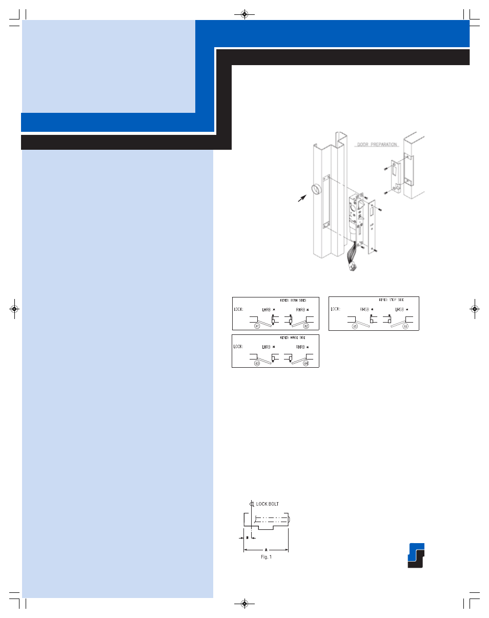
PROVIDE: (See Fig. 1)
1. Dimension “A” (overall frame width)
2. Dimension “B” (edge of frame to
centerline of lockbolt)
10300M MOTOR OPERATED
ELECTRO-MECHANICAL
DEADLATCH
TECHNICAL DATA:
• STANDARD FINISH:
US32D
• LOCK BODY:
Stainless steel
• FACE PLATE:
Stainless steel
• LATCHBOLT:
Stainless steel
• DEADLOCK ACTUATOR:
Stainless steel
Frame Preparation
NOTE: Drawing for illustration only. Reference template
for specific Information.
Swing Chart:
Specify circled swing number when ordering.
• ELECTRICAL: 24 VDC
, Inrush: .3A
Locked Rotor Current: 1.5A
• LOCK SIZE:
10-5/8” H x 1-1/2” W x 1-3/4” D
• LOCK WEIGHT: 3.6 lbs.
• LATCHBOLT SIZE:
1-5/8" H x 5/8" TK
• LATCHBOLT THROW: 3/4"
• BUILDER’S CYLINDER:
1-5/32" diameter with
standard Yale cam or equal
• UL Listed for use
on three-hour fire doors.
• ASTM F 1577 Certified
Impact Test-Grade 1
B16
E L E C T R I C L O C K S
JAMB MOUNTED FOR
SWINGING DOORS
Minimum and medium security.
1-11/16” O.D. x 1/8”
wall cold drawn tubes
are required.
See Note 1
090604SouthernFolger_final:INSIDE 8/21/09 5:22 PM Page 26