LockeyUSA TB100 User Manual
Page 2
T
T
U
U
R
R
T
T
L
L
E
E
B
B
A
A
C
C
K
K
T
T
B
B
1
1
0
0
0
0
H
H
Y
Y
D
D
R
R
A
A
U
U
L
L
I
I
C
C
G
G
A
A
T
T
E
E
A
A
N
N
D
D
D
D
O
O
O
O
R
R
C
C
L
L
O
O
S
S
E
E
R
R
between the Hinge Bracket
and insert a Hinge Bolt,
secure with a Nut. Slightly
open the door or gate to get
the proper hinge alignment
then connect the other Hinge
Knuckle to the Anchor Bar,
Insert Hinge Bolt and secure
with a Nut.
5. Open the door or gate and remove the Wing Key from
around the Piston Rod. This will allow the door or gate to
close properly. Save the Wing Key, as it must be reused
should it be necessary to remove the Hydraulic-Spring
Assembly. Open the door or gate and allow the Turtle Back
to shut the door or gate. The Adjusting Screw (Dia.3)
controls the closing speed of the door or gate. Turning
clockwise slows the closing rate, counterclockwise to
increase the speed. (Note: Increase speed to overcome a
lock set with a strong latch spring)
6. Snap on the Cover over the hydraulic cylinder with the
curved section up. Your installation is now complete.
ADDITIONAL MOUNTING INSTRUCTION FOR CHAIN LINK AND
METAL GATES:
With so many different types of metal door and gates-chain link,
ornamental iron, etc. the installer may have the need for additional
mounting plates (not included) and to adapt the instructions to their
application.
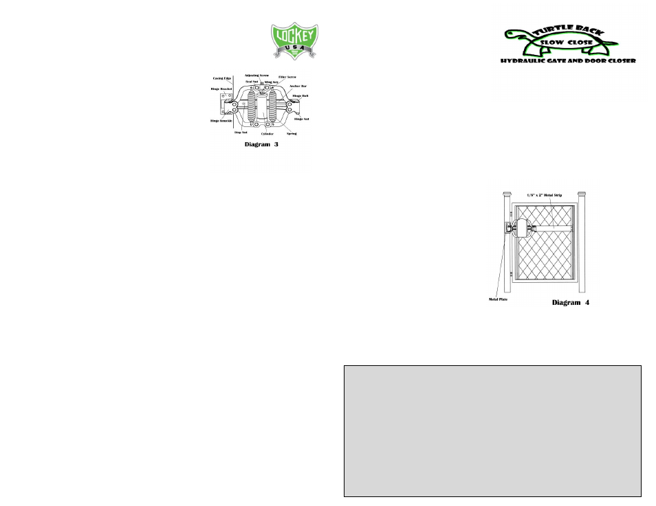
ALTERNATE METAL POST
INSTALLATION: (Dia. 4)
Round metal post: Weld an “L” angle or plate to the post so the
mounting surface is parallel to the door or gate in the closed
position. Align per instruction and clamp the Hinge Bracket to the
new plate. Then bolt (not included) or weld into place.
Flat or square metal post: Locate desired mounting location, align
Hinge Bracket per instructions and
bolt or weld into place.
ALTERNATE METAL GATE
INSTALLATION (Dia.4)
Some metal gates do not have the
proper mounting surface; for
example as with a chain link gate. A
wooden or metal strip (not
included) wide enough to mount
the Anchor Connector Plate (approximately 2”) will be needed. Bolt
or weld the strip horizontally side to side across the gate’s wire
mesh. Now following the INSTALLATION PROCEDURE step #2 the
Anchor Connector Plate can now be mounted to the gate.
LIMITED WARRANTY Lockey Digital Systems, Inc. (LDS) warrants the TURTLE BACK CLOSER for 6 months
from the date of purchase, only to the original purchaser, against defective material and workmanship.
Lockey Digital Systems, Inc.’s obligation under this warranty is limited to the repair or replacement, at its
option, of the product or any parts thereof, when LDS determines in good faith that the defect is due
solely to materials and/or workmanship, and is conditioned upon payment by the purchaser of all
transportation cost incident to such repair or replacement. Return the product or parts thereof, with
proof of purchase date, to Warranty Department, Lockey Digital Systems, Inc., 116 W. Michigan, Mt.
Pleasant, MI 48858. LDS reserves the right to levy a service charge for handling, packaging and
refinishing the product or parts thereof. This warranty does not include the cost of any inconvenience or
property damage due to the failure of the product, transportation damage, misuse, abuse, accidents or
similar incidents. This warranty gives you specific legal rights and you may also have other rights which
vary from state to state. This warranty replaces all previous warranties and is the only warranty made by
LDS on this product. No other warranties, either verbal or written, are authorized.