Lockey m-series how to change code – LockeyUSA M210 EZDC User Manual
Page 2
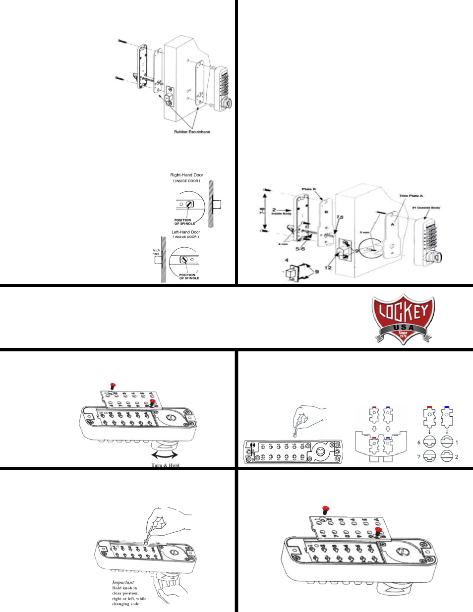
M210 EZ Installation Instructions
The M210 EZ is designed for doors with standard 2 1/8” prep
1. Determine door handing. Refer to Step #3 on reverse side.
2. Place the Outside Body #1 on EZ-Plate A (shown below) and screw
into place with two (2) M5 x 1/2” screws.
3. Place the Brass Support Pin (#15) into Plate B on either side.
4. Install Adjustable Deadbolt into door. Refer to Step #4 on reverse
side.
5. Place Plate A with Outside Body attached to outside of door. Place
Plate B to the inside of door making sure Support Pin fits through hole
in the Deadbolt. Hold tight to door and secure using two (2) M4 x 35
mm. or M4 x 50 mm. screws.
6. Place the Spindle (#7 or #8) into the large hole in Plate B, through the
Deadbolt and into the Outside Body. Refer to Step 6 on reverse side
and Step 7 (to left) to verify correct spindle length and position.
7. Place Inside Body to Plate B and secure using two (2) screws.
8. Test the operation of the Deadbolt by turning the inside thumbturn.
Step 7 cont: Install the Lockey M210
1. Insert the Spindle (#5/6) into the Outside
Body (#1) ensuring it’s in the
proper angled position.
*(SEE FIGURES BELOW)
2. Using a screwdriver, secure
the lock to the door with
the Screws (#7 or #8).
Screw length dependent on
door thickness.
3. Test the operation of the
Deadbolt by turning the inside thumbturn.
4. Locate position where Deadbolt strikes door frame
And install Mortised Strike (#4).
*IMPORTANT: SPINDLE POSITION/ANGLE
RIGHT-HAND DOORS: From inside,
place spindle through Deadbolt, into the
Outside Body (#1) in the 2:00/8:00
position as shown to right.
LEFT-HAND DOORS: From inside,
place spindle through Deadbolt, into the
Outside Body (#1) in the 10:00/4:00
position as shown to right.
6. Replace the cover plate and secure with two (2) Red Screws,
using a #2 screwdriver.
7. TEST CODE before installing/re-installing lock.
4. With the thumb-turn held to right or left, remove/add
CODE (Red)
and
NON-CODE (Blue)
Tumblers to create your desired code.
Ex: 3 Red = 3-Digit Code / 6 Red = 6-Digit Code
IMPORTANT: Ensure notched side of tumbler fits into slot. (Below – Far Right).
5. After changing your code, release the thumb-turn to secure the tumblers
in place.
3. TURN & HOLD thumb-turn to right or left to release tumblers.
IMPORTANT: THUMB-TURN MUST be turned and held when removing
and inserting tumblers. Failure to do so will damage the lock and void
the warranty.
Lockey M-Series
How to Change Code
1. Using a #2 screwdriver, remove the two (2) Red Screws.
2. Carefully remove cover plate.
WARNING: Springs are attached to plate.
RED = CODE TUMBLERS
BLUE = NON-CODE TUMBLERS
WARNING:
Do NOT force tumblers into position!
TURNING THUMB-TURN =
CLEAR POSITION