Cq series signal cable connectors – JuiceGoose CQ Series - Power Sequencers User Manual
Page 8
OPERATION
These versatile CQ devices can be controlled by way of either another CQ
device, a remote latching contact closure, a Juice Goose RC5 accessory
unit or the switch on the CQ device itself (except the CQ 1).
CQ DEVICES - Any CQ device can operate in concert with others. Each
can be a master (except the CQ 1) or slave unit. Any number of CQ de-
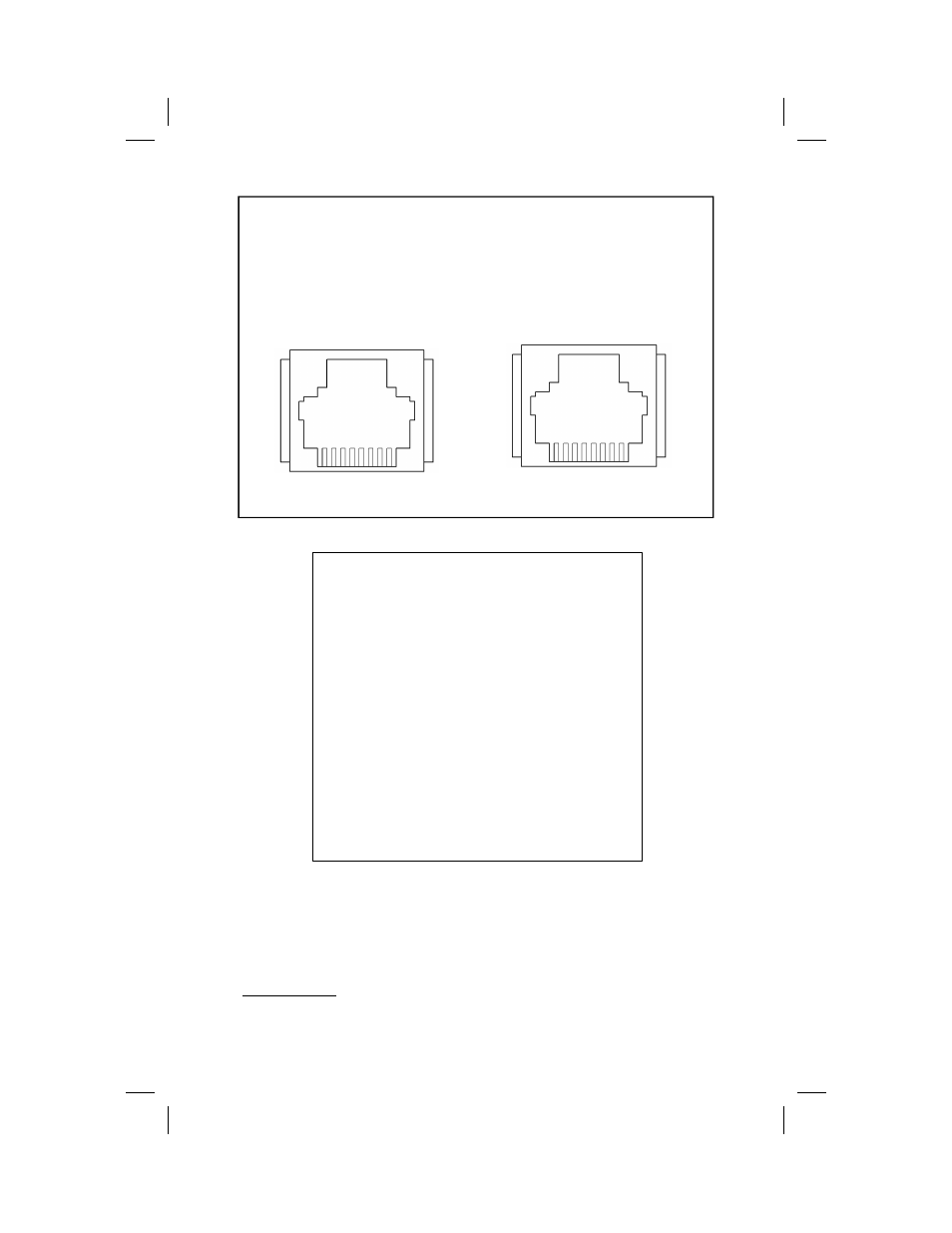
8 7 6 5 4 3 2 1
1 2 3 4 5 6 7 8
PIN ASSIGNMENTS
The chart above shows assigned locations for each
of the eight pins on the RJ45 connectors on the CQ
Series Signal Input and Output. Note: although
there are eight pins, only the middle six are being
used.
This information may be used to connect a latching
contact, as per the diagram on the previous page.
It also illustrates the reversed orientation of the
connectors on each end of a CQ signal cable.
Pin assignments are correct when viewed from the
outside of the chassis.
Signal
Input
Signal
Output
CQ Series
Signal Cable Connectors