Signal cable assembly – JuiceGoose CQ Series - Power Sequencers User Manual
Page 6
labeled. Attach the front panel (containing the circuit board) to the back box
using all seven screws. Gently pull excess cable length out of the box by
tugging slightly on the cable from the outside of the box. Insert conduit into
squeeze connector and tighten the connector to hold the conduit in place.
CQ-PD1-4 - The CQ-PD1-4 has two slotted side brackets that can be relo-
cated along the length of the chassis. Use only appropriate hardware (not
included) and use four mounting holes to secure the device. The wire har-
ness should be connected directly to a circuit breaker panel or to an appro-
priate junction box.
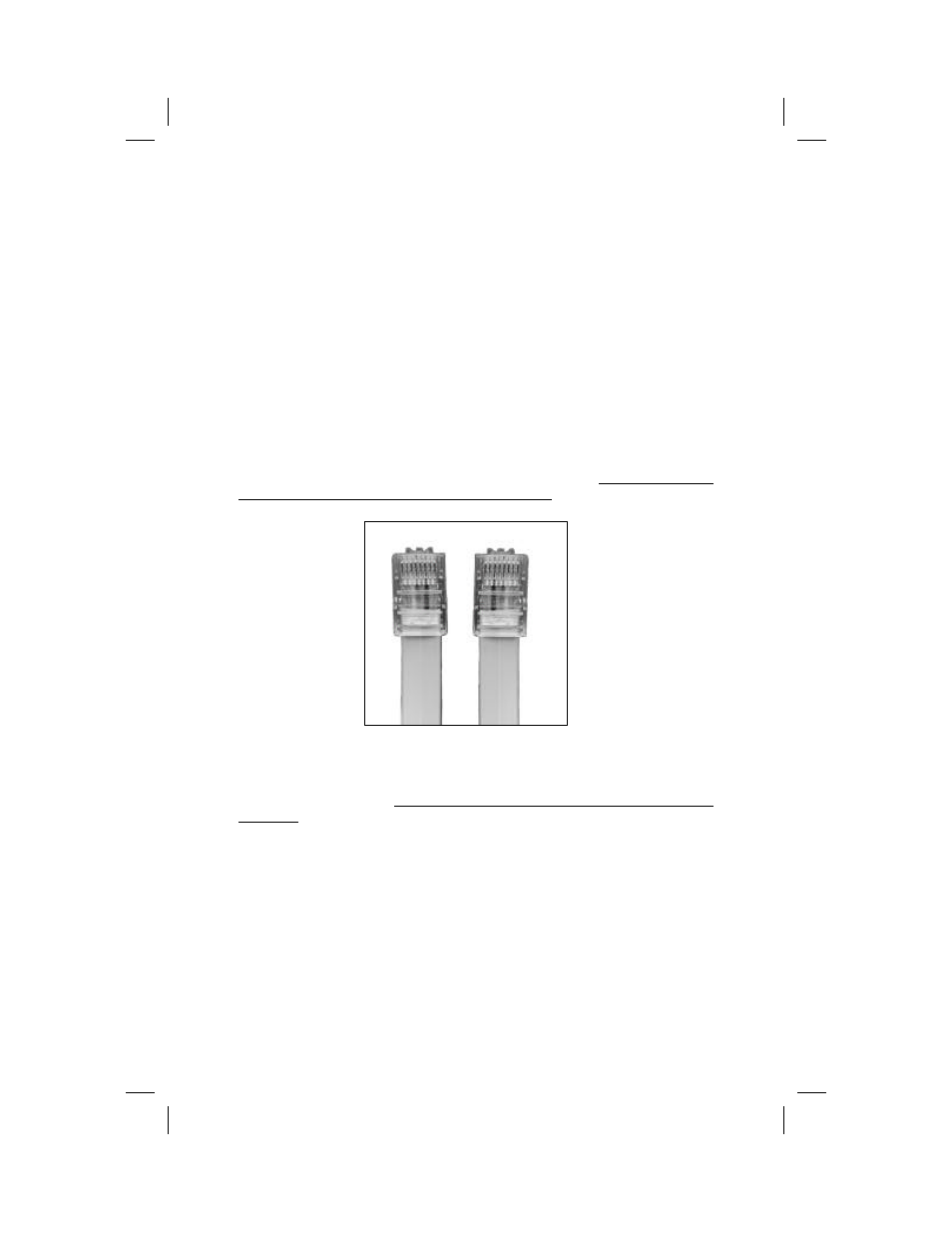
SIGNAL CABLE ASSEMBLY
The interconnecting CQ Series devices requires eight wire, RJ-45 cable.
While this is the same component used to assemble CAT5 and CAT6 ca-
bles, orientation of the connectors on the CQ Series cable is slightly differ-
ent than for the CAT data networking cable. Therefore, standard CAT5 or
CAT6 cables will not work with CQ Series devices.
After crimping a RJ45 connector on one end of the eight wire cable, attach a
connector on the other end “upside down” from the first so that when the
connectors are placed side by side the wire orientation will appear as shown
in the above illustration. Check the cable with a continuity tester prior to in-
stallation.
There is no known distance limit for the connection of CQ units by means of
this cable system. The CQ signal is not sensitive to voltage changes or fre-
quency interference.
1 2 3 4 5 6 7 8
8 7 6 5 4 3 2 1